Installation and Commissioning
8-157SJ62 Manual
C53000-G1140-C121-1
8.2 Checking Connections
8.2.1 Data Connections
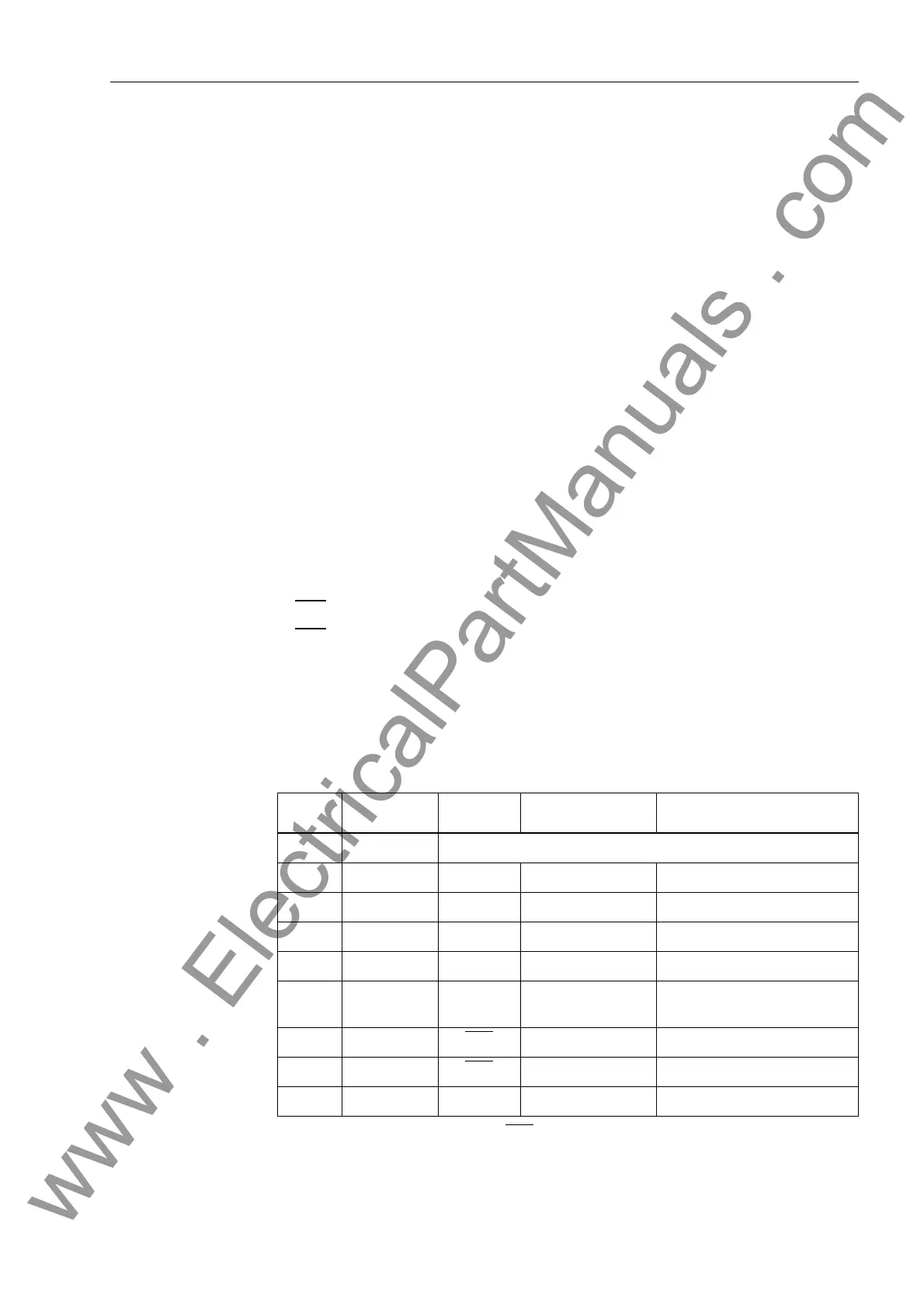
Table 8-7 shows the pin-assignments for the various serial interfaces of the device.
Table 8-8 refers to the time synchronization interface.
PC Interface at
Front
When the recommended communication cable is used, correct connection between
the SIPROTEC
®
device and the PC is automatically ensured. See the Appendix, Sub-
section A.1.3 for an ordering description of the cable.
SCADA Interface When a serial interface of the device is connected to a SCADA, the data connection
must be checked. A visual check of the transmit channel and the receive channel is
important. Each connection is dedicated to one transmission direction. The data out-
put of one device must be connected to the data input of the other device, and vice
versa.
The data cable connections must conform to DIN 66020 and ISO 2110 (see also Table
8-7):
− TxD data transmit
− RxD data receive
− RTS
request to send
− CTS
clear to send
− DGND signal/chassis ground
The cable shield is to be grounded at only one end so that potential differences cannot
cause circulating currents to flow along the shield.
*) Pin 7 also can carry the RS 232 RTS signal to an RS 485 interface. Pin 7 must therefore
not be connected!
Table 8-7 Installation of the D-Subminiature Ports
Pin No. PC Interface
at Front
RS 232 RS 485 Profibus FMS Slave, RS 485
1 Shield (with shield ends electrically connected)
2RxDRxD ––
3 TxD TxD A/A’ (RxD/TxD–N) B/B’ (RxD/TxD–P)
4 – – – CNTR–A (TTL)
5 DGND DGND C/C’ (DGND) C/C’ (DGND)
6 – – – + 5V voltage supply
(max. load < 100 mA)
7–RTS
–*) –*)
8–CTSB/B’ (RxD/TxD–P) A/A’ (RxD/TxD–N)
9– – – –
www . ElectricalPartManuals . com
 Loading...


