Routine Checks and Maintenance
9-57SJ62 Manual
C53000-G1140-C121-1
o Carefully pull off the front panel. The front panel is connected to the internal CPU print-
ed circuit board with a short ribbon-cable.
o At one end, disconnect the ribbon-cable between the front panel and the CPU board.
To disconnect the cable, push up on the top latch of the plug connector and push down
on the bottom latch of the plug connector. Carefully set aside the front panel.
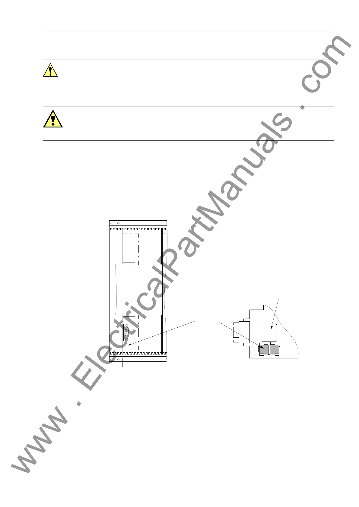
o The battery is located on the bottom-front side of the CPU (¯) board. See Figure 9-1.
Figure 9-1 Front View without Front Panel – Position of Buffer Battery (simplified and re-
duced)
o Remove the old battery from the snap-on connector using the plastic battery grip
shown in Figure 9-1.
o Remove the battery grip from the old battery, and place the grip on the new battery.
Caution!
Electrostatic discharges through the connections of the components, wiring, and con-
nectors must be avoided. Wearing a grounded wrist strap is preferred; otherwise,
touch a grounded metal part before handling the internal components.
Warning!
Hazardous voltages can exist in the device, even after disconnecting the power supply
or withdrawing the boards! Capacitors can be charged.
¯ Processor Board CPU
° Input/Output Board I/O
¯
Slot 5 Slot 19
G1
+
–
°
Battery
Battery Grip
www . ElectricalPartManuals . com
 Loading...


