 Loading...
Do you have a question about the Siemens Sitrans LR250 and is the answer not in the manual?
| Accuracy | ± 2 mm |
|---|---|
| Power Supply | 10.5 to 42 V DC |
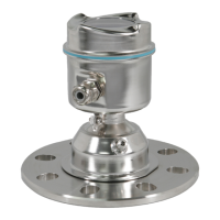
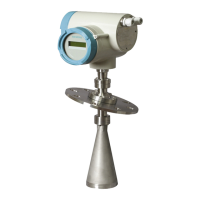
| Measurement Principle | Radar |
| Process Temperature | -40 to +80 °C |
| Process Pressure | Up to 40 bar |
| Output Signal | 4 to 20 mA HART |
| Communication | HART |
| Enclosure Rating | IP68 |
| Housing Material | Aluminum, stainless steel |
Stresses observing instructions and device symbols for safe operation.
Details qualifications required for personnel working in hazardous areas.
Gives general notes and notices for correct mounting procedures.
Details nozzle design requirements and recommendations for various antenna types.
Gives warnings about power source and loss of protection due to installation.
Outlines the three wiring options for hazardous areas.
Details intrinsically safe wiring and ATEX certificate information.
Lists ATEX directive instructions for equipment safety in hazardous areas.
Provides notes and instructions for using the Quick Start Wizard.
Introduces SIMATIC PDM as a software for device commissioning and maintenance.
Explains how to configure a new device using SIMATIC PDM.
Guides through the Quick Start wizard using SIMATIC PDM.
Explains how to change parameter settings using SIMATIC PDM.
Provides notes on parameter names, menu structure, and quick access.
Lists parameters related to Quick Start, Language, Material, Response Rate, Units, and Operating Mode.
Details Material, LOE Timer, and Calibration parameters.
Explains Low Calibration Pt. and High Calibration Pt. parameters.
Details Response Rate, Fill Rate, and Empty Rate parameters.
Explains Linearization and Vessel Shape parameters.
Covers Near Range and Far Range parameters for signal processing.
Details TVT Setup and Auto False Echo Suppression parameters.
Explains how to set the PROFIBUS address and notes on address lock.
Provides safety warnings regarding impermissible repair and releasing key locks.
Outlines periodic inspection points and safety warnings for maintenance in hazardous areas.
Provides steps to troubleshoot communication issues, including wiring and addresses.
Lists general fault codes, their meanings, and corrective actions.
Details common operating symptoms, causes, and resolutions.
Explains the signal processing technology known as Process Intelligence.
Explains Echo Threshold and Echo Lock parameters.
Introduces Auto False Echo Suppression and its purpose.
Details Near Range and Far Range parameters for measurement.
Explains Measurement Response and Damping parameters.
Explains Loss of Echo (LOE) and its conditions.
Explains PROFIBUS address identification and setting.