User Manual
EM303A General Purpose Inverter
114
★ Customer can set the current
limit based on actual needs to
protect motor or meet the
working requirements.
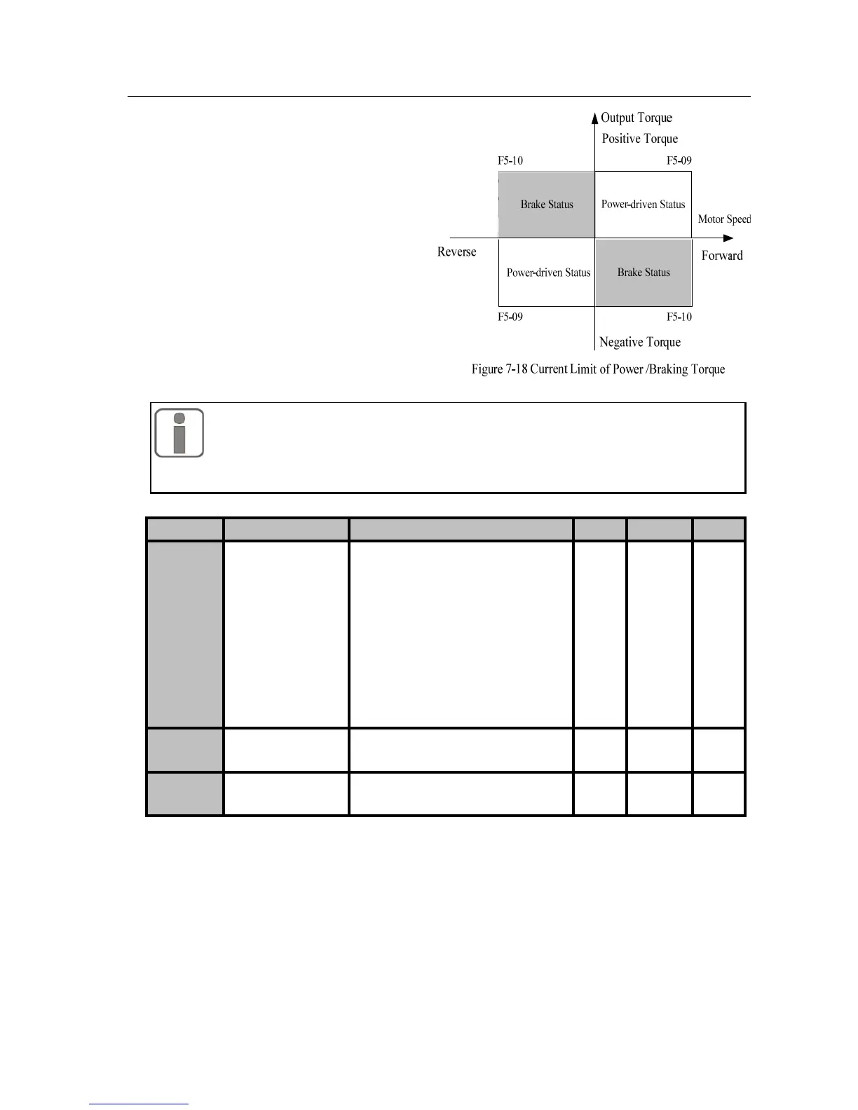
F5-09 and F5-10 limit the torque
limiting current in power-driven
and brake status respectively. See
Figure 7-18.
1. If the setting torque current and rotation of motor are in the same
direction, the torque current is the power torque current.
2. If the setting torque current and rotation of motor are opposite, the torque
current is the brake torque current.
No. Function Range Unit Default Type
F5-11
Regular Torque
Setting
0: Primary Numeric Torque Setting
1: VP
2: VS
3: IS
4: VF
5: IF
6: Not Used
7:K1*VP+K2*(K3*VS+K4*IS+K5
*VF+K6*IF-K8*5V)
0 〇
F5-12
Primary Numeric
Torque Current
0.00~150.00 % 0.00 ●
F5-13 Torque Direction
0: Positive Torque
1: Negative Torque
0 ●
Torque Setting Channel Options
F5-11=0 Numeric torque current setting. Input the setting value of torque current
through editing F5-12 parameters through keypad.
F5-11=1 Keypad potentiometer sets the VP input voltage as the setting value of torque
current.
F5-11=2 Input voltage of analog input terminal VS is the setting value of torque
current.
F5-11=3 Input current of analog input terminal IS is the setting value of torque current.
F5-11=4 Input voltage of analog input terminal VF is the setting value of torque
current.
 Loading...

