User Manual
EM303A General Purpose Inverter
36
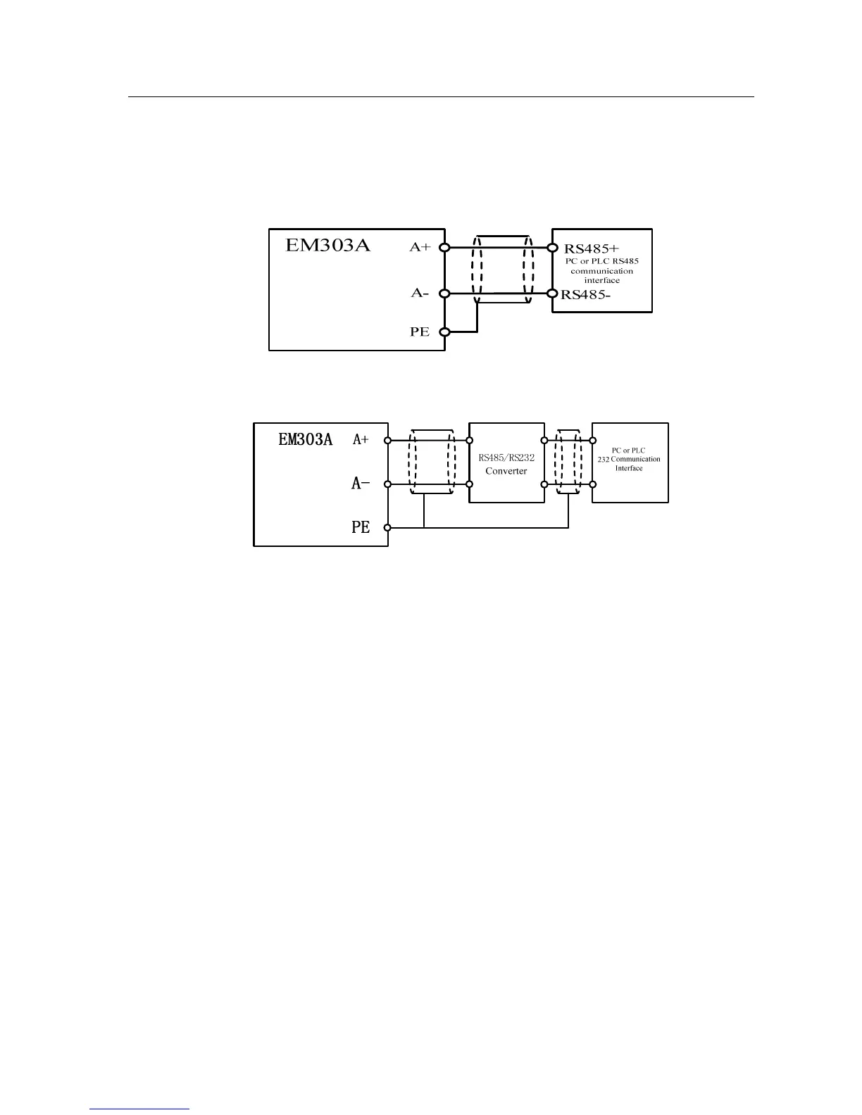
3.3.2.6 Wiring Communication Terminal
Terminals A+ and A- are the RS485 communication interfaces of the inverter.
The control network between PC or PLC and inverter can be achieved through
connecting communication with PC or PLC. See Figure 3-15 and Figure 3-16 for
connection of RS485, RS485/RS232 converter and EM303A.
z Connect to PC or PLC through RS485 terminal:
Figure 3-15 Wiring of Communication Terminals
z Connect to PC or PLC through RS485/RS232 interface converter:
Figure 3-16 Wiring of Communication Terminals
3.3.3 Size of Control Circuit Cable and Screw
To lower interference and attenuation of control signal, the cable length of control
signal should be in a maximum of 50m, and the distance should be in a minimum
30cm between the signal cable and the power cable. Twisted-pair cable or shielded
cable shall be used when inputting analog signal externally. 0.5~1mm
2
cable as the
control circuit cable should be the best.
There are two types of control circuit wiring terminals for EM303A: clamp
terminal and barrier terminal, install them with a PH0 cross head screwdriver. The
tightening torque of screw is 0.5N.m. Please pay attention to followings based on
different features of these two terminals:
z Clamp wiring terminal
Take pin terminal or cable strip length by 5~7mm for connection.
Only after the terminal screw is fully loosened anticlockwise first, the cable can
be inserted.
z Barrier wiring terminal
Take a circular or a U-type clamp terminal with holes of 3.5mm.
3.3.4 Control Circuit Wiring Precautions
z
Separate the control circuit cable from the other cables.
z Separate the cables of control circuit terminals EA, EB, EC, Y1, and Y2 from the
cables of other control circuit terminals.
z Use shielded twisted-pair cables for control circuit to prevent malfunctions. The
wiring distance should be in a maximum of 50m.
z Wrap the shield net with insulating tape to prevent the shield net from contacting
with other signal cables and housing of device.
 Loading...

