User Manual
EM303A General Purpose Inverter
131
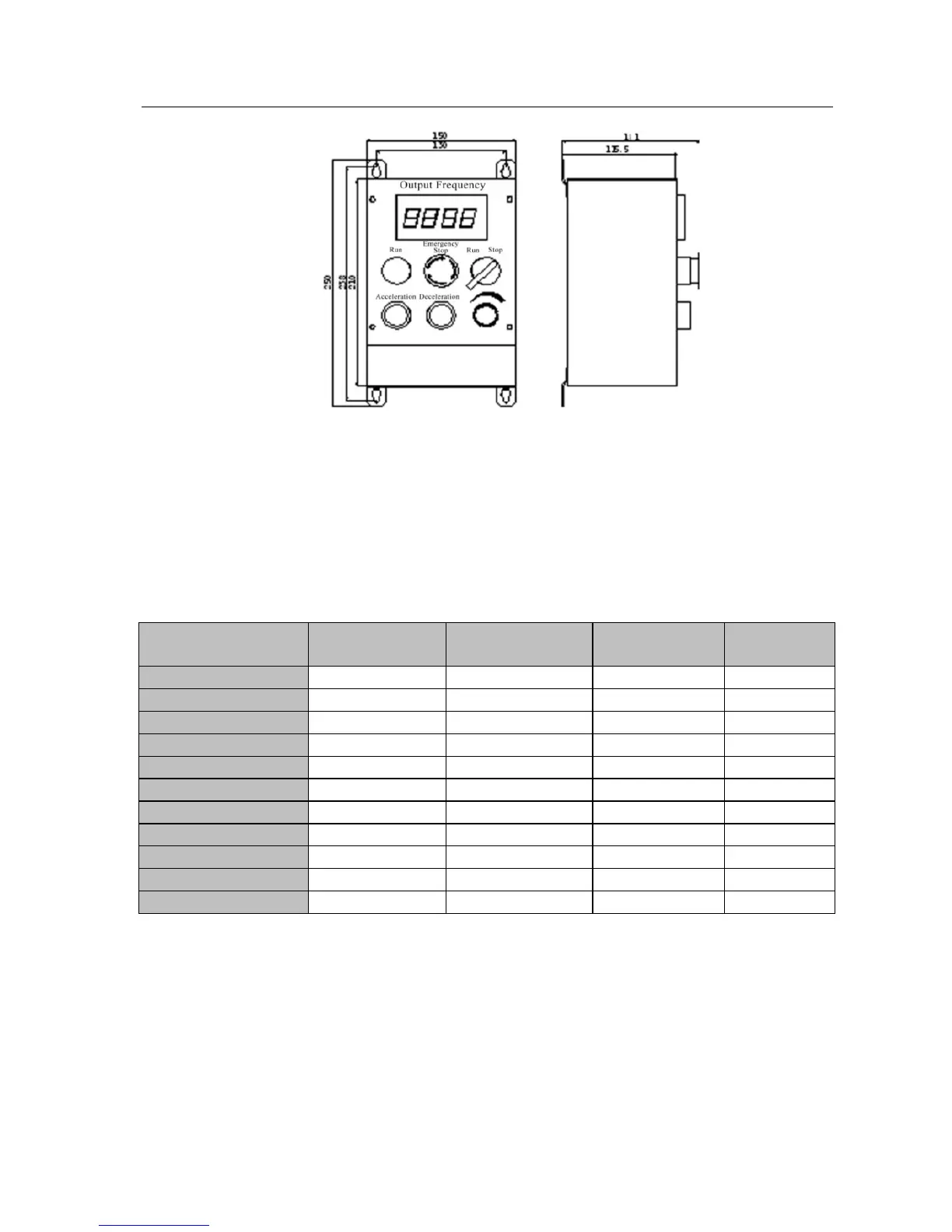
See Figure 11-1 for the overall and installation dimensions of remote operation case.
Figure 11-1 Outlook and Installation Dimensions of Remote Operation Case
11.3 Braking Resistor
EM303A (0.75~15KW) with an integrated braking unit can be connected to
braking resistor directly for quick stop. Refer to Table 11-1, and select braking
resistor for EM303A.
Table 11-1 Braking Resistor Selection
Inverter Model No.
Motor Power
(kW)
MIN Resistor
Resistance(Ω)
Resistor power
(W)
Cable Size
(mm
2
)
EM303A-0R7-3CB 0.75 ≥360 ≥200 1
EM303A-1R1-3CB 1.1 ≥360 ≥200 1
EM303A-1R5-3CB 1.5 ≥180 ≥400 1.5
EM303A-2R2-3CB 2.2 ≥180 ≥400 1.5
EM303A-3R0-3CB 3.0 ≥180 ≥400 1.5
EM303A-4R0-3CB 4.0 ≥90 ≥800 2.5
EM303A-5R5-3CB 5.5 ≥60 ≥1000 4
EM303A-7R5-3CB 7.5 ≥60 ≥1000 4
EM303A-9R0-3CB 9.0 ≥60 ≥1000 4
EM303A-011-3CB 11 ≥30 ≥2000 6
EM303A-015-3CB 15 ≥30 ≥2000 6
Remarks:
1. See User Manual of BR100 Braking Unit for selecting braking resistor for
EM303A-018 or above.
2.
Cables listed in above table refer to the lead cable of single resistor. The DC bus should
be uprated if the resistors are in parallel connection.
3.
Cable should withstand voltage≥AC450V, temperature resistance :105℃.
4.
Because there is a resistor limit of power consumption, the longest operation time for
10%ED is 10S (On: 10S/ Off:90S).
 Loading...

