User Manual
EM303A General Purpose Inverter
26
3.2.2 Main Circuit Terminal Functions
The main circuit terminal functions of EM303A are listed in Table 3-1. Wire the
terminals correctly as per corresponding function.
Table 3-1 Main Circuit Terminal Functions
Terminal Function
R, S, T AC power input terminals for connecting to 3-phase AC power.
(Terminal L1, L2 for AC220V 1-phase input inverter)
U, V, W
Inverter AC output terminals for connecting to 3-phase induction motor.
Positive and negative terminals of internal DC bus for connecting to
external braking unit.
PB Connecting terminals of braking resistor, one end connected to and the
other to PB.
Grounding terminals
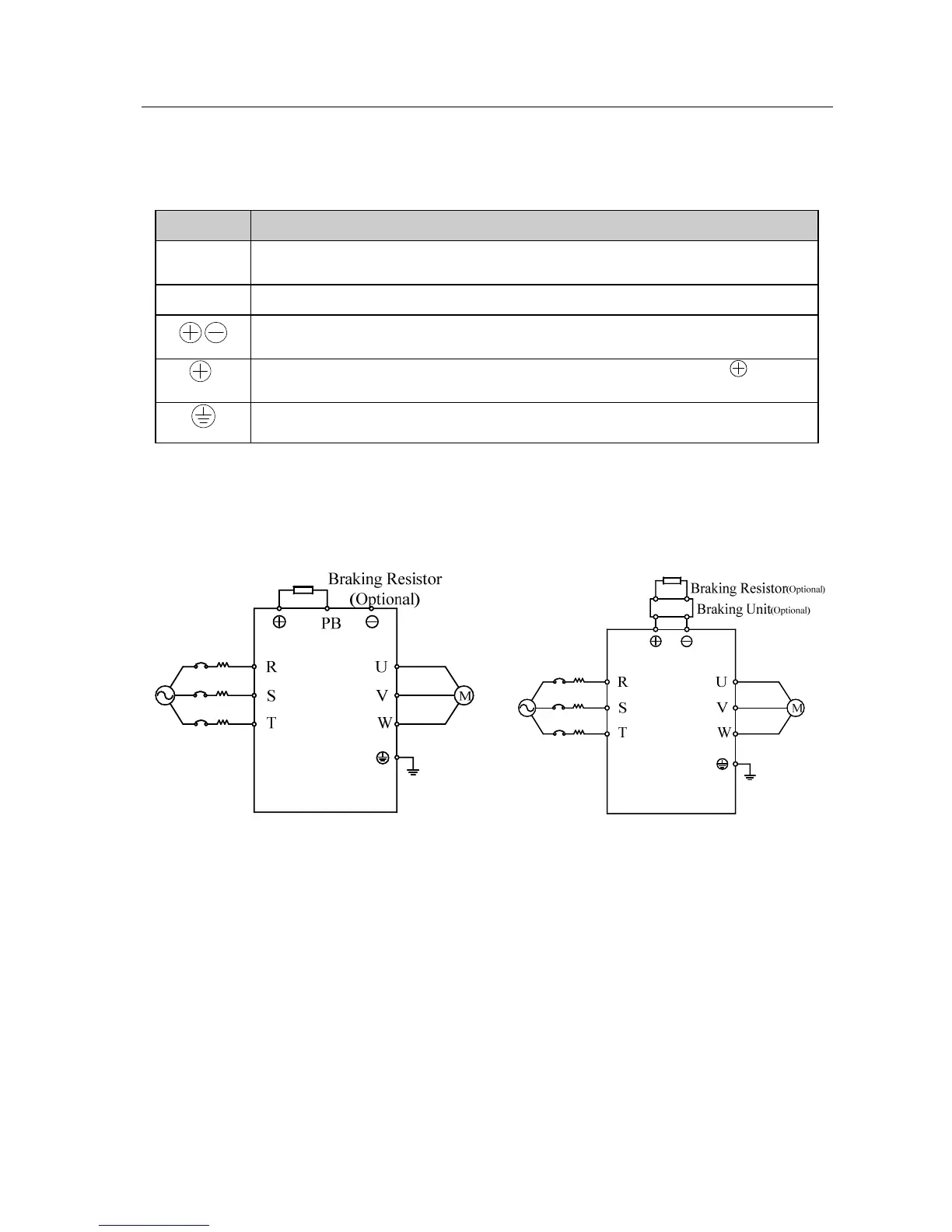
3.2.3 Standard Wiring of Main Circuit
See Figure 3-3 for standard wiring of main circuit.
EM303A-0R7~015
Terminal L1&L2 for inverters with 1-phase AC220V
input
EM303A-018~400
Figure 3-3 Standard Wiring of Main Circuit
3.2.4 Wiring Main Circuit on Input Side
Installing a Circuit Breaker
Always install an air circuit breaker (MCCB) between the power supply and input
terminals.
z Choose a MCCB with a capacity of 1.5-2 times of the inverter’s rated current.
z The time characteristics of MCCB should meet that of inverter’s overheating
protection (150% of rated current /1 minute).
 Loading...

