41
EN
ATYSp - 542001E - SOCOMEC
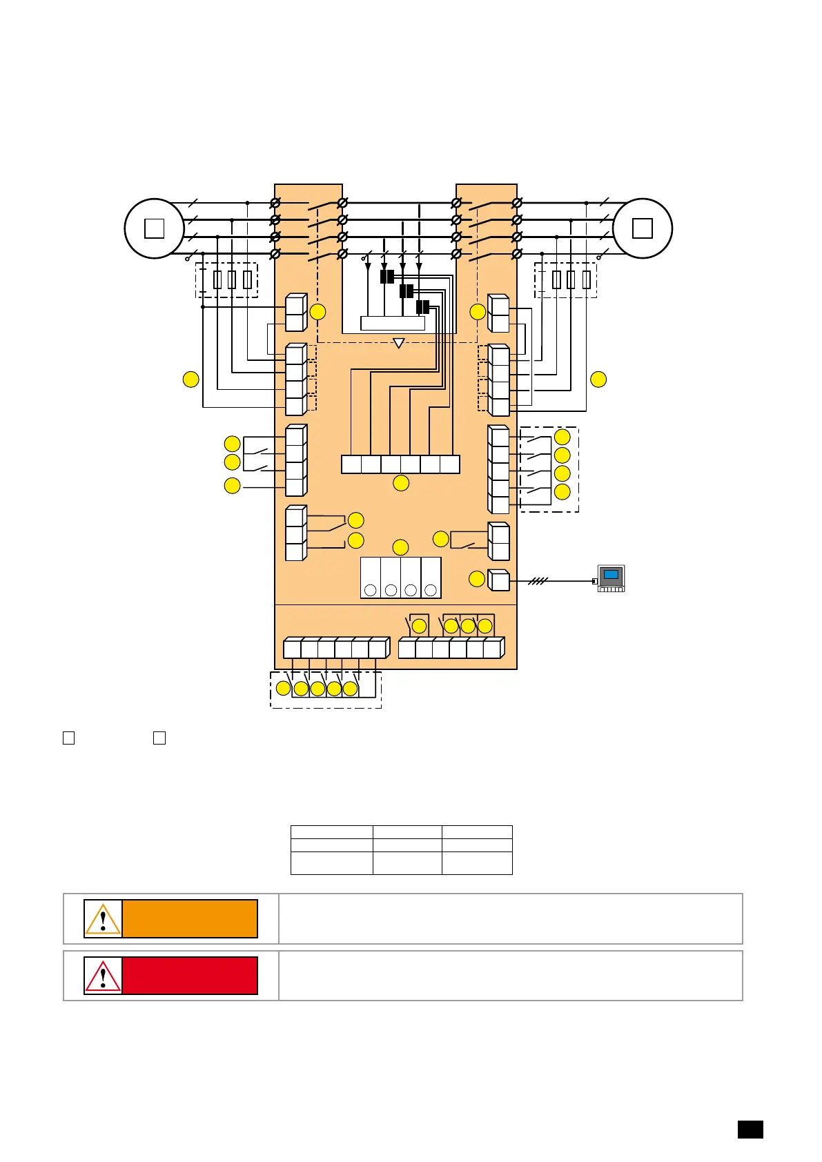
7.3. Control circuits
7.3.1. Typical ATySpwiring
Example: Control wiring for a 400VAC application having a 3 phase and neutral supply.
ATySp Voltage
Sensing and
Power supply Kit
(excludes the need
for fuses F1 & F2
5
6
4
3 2
1
2
7
104 103
312313 314315 316317 63A64A 24 14 04 13
8 9
10
RJ
102 101
105106
414 413415416417
64B 63B
201 202
205 206204203
210209208207
12
13
14
15
11
1
F1
F2
19
20
16
17
18
23
23
24
24
72 71
74
I/1-2 I/3-4 I/5-6 I/7-8
II/1-2 II/3-4 II/5-6 II/7-8
LOAD
21
22
R1 R2 S1 S2 T1 T2
Opt. 3
Opt. 2
Opt. 1
4
Opt. 4
3
2
1
Fus. 4A
type gG
Fus. 4A
type gG
D20
Remote Control /
Display Unit
1
preferred source
2
alternate source
1. Position 0 order
2. Position I order
3. Position II order
4. Zero position priority order
5.
Remote Control Enable (Priority over Auto)
6. Product Available output (Motor)
7. Position II aux contact
8. Position I aux contact
9. Position 0 aux contact
10. O/P to D20 remote unit
11. Programmable Output Contact.
By default set to ATS Product Available -
Normally Open
12-15. Programmable Inputs 1-4
16-17. Programmable Inputs 5-6
18. Aux. Supply (207/210) to be used with ATyS
optional I/O modules
19-20. Genset starting and stopping order
Control 71/72 (19) 71/74 (20)
Generator starting Contact closed Contact open
Generator stop-
ping
Contact open Contact closed
21. Option Module Slots 1 to 4
22. Current Transformer incoming cable
connections
23. Voltage sensing inputs
24. Power supply Inputs
CAUTION
Verify that the Auxiliary power supply feeding terminals 101 and 102 / (201 and
DANGER
Do not handle any control or power cables connected to the ATyS when voltage
may be present.
 Loading...