S6 Portable Digital Color Doppler Ultrasound System
Service Manual
6
Monitor: 15 inch LCD
6
Loudspeakers: Serve as Doppler audio device.
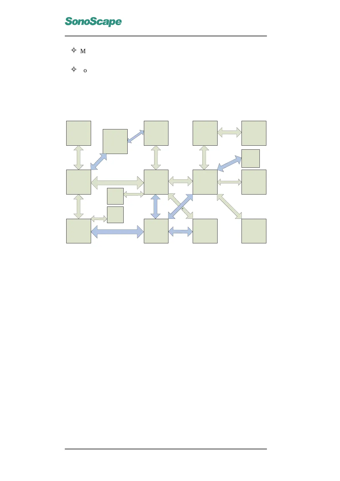
4.5.1 Functional Block Diagram
DBF Board
7500-0821-XX
DBTR Board
7500-0820-XX
DBHV Board
7500-0822-XX
KEAA board
7500-3039-XX
Motherboard
2101-0008
Power Supply HDD
Monitor
KBD board
7500-0813-XX
USB Cable
Power Calbe
IDE Cable
PS2 Cable
S
A
TA
C
a
b
l
e
P
o
w
e
r
Ca
b
l
e
Printer
Loudspeaker
Cable
Printer Cable
F
o
ot
S
w
i
t
ch
C
ab
l
e
Loudspeakers
Foot Switch
VGA Cable
Voltage
Conversion Board
P
o
w
e
r
C
a
b
l
e
Fan
P
o
w
e
r
C
a
b
l
e
VIDEO
OUT
D
a
t
a
C
a
b
l
e
ECG
D
a
t
a
C
a
b
l
e
Power Cable
P
o
w
e
r
C
a
b
l
e
Figure 4.2: Functional Block Diagram
4.5.2 Explanations of the System Functions
The electronic pulse signals are sent to the DBTR board from the RAM
of the DBF board. After processing, DBTR sends the HV signals to drive
the piezo oscillator in the probe. The probe emits the ultrasonic sounds to-
wards patient, and also picks up the echoes. The signals are then processed
by the front end amplifier and the TGC, both on the DBTR board. At the
same time, the DBF board converts the analog signals to the digital signals,
utilizes the digital dynamic receive focusing and dynamic tracing technolo-
gies, and then demodulates. With some further processing, the signals
carrying image information are transmitted to the computer through high
speed USB2.0 connection. The computer processes the image data, and
the tissue and/or blood flow information is displayed on the screen. The
computer also takes user inputs from the keyboard, and sends the control
signals to the DBF board through USB2.0 port. Peripherals and Ethernet
ports are available on the Motherboard. The switching power supply for
medical use provides 12V and 5V DC outputs to other system units/boards.
The DBHV board supplies 90V DC and the low voltages for other digital
and analog circuits.
P/N: 4720-0034-01A
4-4

 Loading...