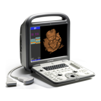
S6 Portable Digital Color Doppler Ultrasound System
Service Manual
8.2.8 Probe ID, HV and Temp
This test includes three elements:
1. Identify the probe ID; 255 is displayed if no probe is connected.
2. It tests the functionalities of HV generator and HV regulator.
3. It checks the temperature of HV generator.
Refer to DBHV test for the pass/fail standard of this test.
8.2.9 ADC Test (Rx off)
Run this test only if the DBTR board is not installed and receive channel is
off (Rx off)! Refer to 8.2.7 for ADC test details.
8.2.10 Receive Channel Test
It displays illustration of the functionality of the 64 ADC channels on DBF
board. This test requires the normal operation of the back ends (demodula-
tion and scanning units). So the illustration is also an indication of whether
the back ends work normally.
8.2.11 Single Element Test
Test the output signal channels from probe to demodulator. The probe for
this test has an input either from echoes (by submerging the probe head
into a cup of water) or from external ultrasound generator. An illustration
will be displayed after running the single element test. The cause of the
error, if any, can be identified from this illustration to be the probe board,
the array elements or the DBTR board.
Note: In the Service Center, a simulation probe may be used instead. The
simulation probe is a probe with a simulative load and is connected to
an oscilloscope. By observing the test results from the oscilloscope, the
problem of the output signal channels from probe to demodulator can be
identified.
8.3 Test Procedures
At the EXAM screen, enter the System Configuration window by pressing
MENU key. Select System Information and press SET key. The system
information will be shown as below,
P/N: 4720-0034-01A
8-3

 Loading...