S6 Portable Digital Color Doppler Ultrasound System
Service Manual
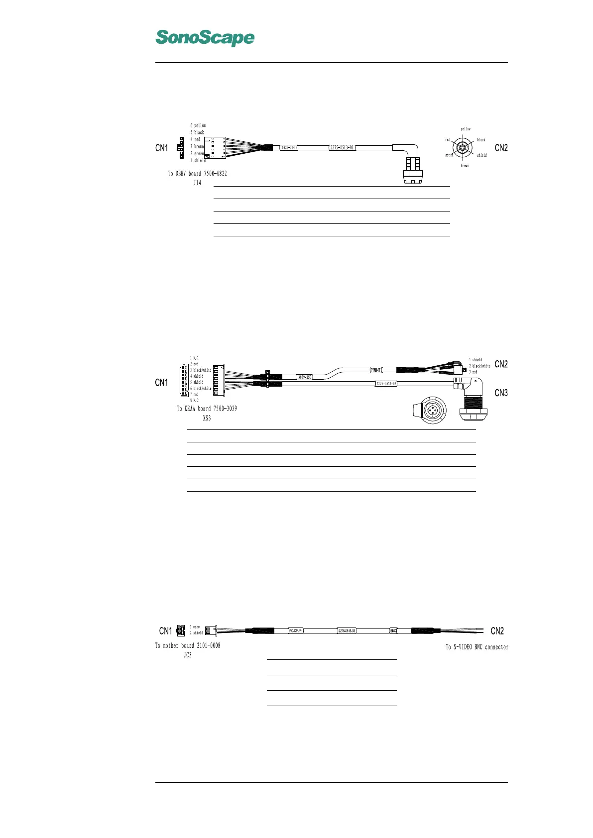
6.3.13 ECG internal connection cable (3520-0513)
Signal RA LA LL GND
Color shield green brown red black yellow
CN1 1 2 3 4 5 6
CN2 6 4 5 3 1 2
Connection Instructions:
Connect CN1 to J14 on the DBF board and CN2 to the ECG connector on
the back panel.
6.3.14 Foot Switch Cable (3520-0514)
Signal GND FSW2 FSW1 GND GND PRT-BVSY PRT-CTRL GND
Color NA red black/white shield shield black/white red NA
CN1 8 7 6 5 4 3 2 1
CN2
CN3 2 3 1,4
Connection Instructions:
Connect CN1 to XS3 on the KEAA board. Connect CN2 and CN3 to the
printer socket and the foot switch socket respectively on the rear IO panel.
6.3.15 Composite Video BNC Cable (3520-0515)
Color Core Shield
CN1 Core BNC shell
CN2 1 2
Connection Instructions:
Connect CN1 to JC3 on the motherboard. Attach CN2 to the back panel as
VIDEO-OUT port.
P/N: 4720-0034-01A
6-9

 Loading...