S6 Portable Digital Color Doppler Ultrasound System
Service Manual
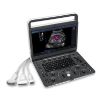
6.3.8 Cables Connecting Keyboard and motherboard (3520-0508)
Signal GND Audio L Audio R GND POWSWL POWSWR GND KBDATA KBCLK GND
Color Black Violet Brown NC Green Green NC Blue Orange Black
CN1 14 13 12 11 10 9 8 7 6 5
CN2 1 4 2
CN3 1 2
CN4 2 1 4
Connection Instructions:
Connect CN1 to XS2 on the KEAA board. Connect CN2 to EKBM1 on the
motherboard. Connect CN3 to the 9th and the 10th pins of J3 on the
motherboard. Connect CN4 to SOUT1 on the motherboard.
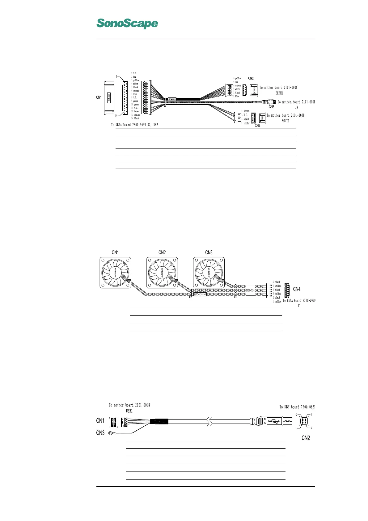
6.3.9 Connection wires for system fan(3520-0509)
Signal +12V GND +12V GND +12V GND
Color yellow black yellow black yellow black
CN1 1 2 3 4 5 6
Connection Instructions:
Attach CN1, CN2 and CN3 to their corresponding designated brackets hold-
ing the fans. Connect CN4 to J1 on the KEAA board.
6.3.10 DBF USB Signal Cable (3520-0510)
Signal +5V D- D+ GND NC GND
Color red white green black no pin shield
CN1 1 3 5 7 10
CN2 1 2 3 4 Metal shell
CN3 GND pin
P/N: 4720-0034-01A
6-7

 Loading...