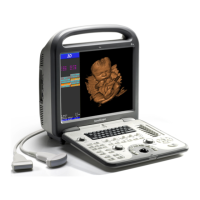
S6 Portable Digital Color Doppler Ultrasound System
Service Manual
6.2 Wiring in the System Level
Please also refer to the schematic diagram attached in appendix B of this
service manual for connection.
Refer to table on page 4-5 to find the part
numbers of the main PCB boards .
Refer to the contents table on page 6-1 to
find the part numbers of the wires/cables .
Connector identification numbers, normally
in the form of ‘J#’, are marked on the cor-
responding PCB boards. Connectors on the
motherboard are indicated in figure 6.1 on
page 6-3.
Warning!
ã Connect the DBF board and the USB port on the Moth-
erboard:
● Incorrect connection may lead to burning the DBF
board!
● Ensure that the connectors are attached firmly.
ã The two connectors of the power switch must be
plugged into the correct sockets on the motherboard.
It’s highly recommended to take note of the positions
before removing the two connectors. Incorrect con-
nection will lead to system startup failure.
ã The connectors on the KEAA board are complex. Some
ports or connectors look alike and can be easily mixed
up. It’s highly recommended to take note of the posi-
tions before removing these connectors. Bad connec-
tions will lead to system malfunction.
P/N: 4720-0034-01A
6-2

 Loading...