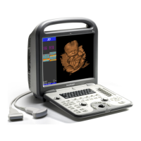
S6 Portable Digital Color Doppler Ultrasound System
Service Manual
5. Press M key to enter M mode, press UPDATE key to ensure that the
system is working properly in M mode. Make sure that TGC, depth
and power control are adjustable. Consult the user manual, if you do
not know how to adjust these parameters.
6. Press PW key to enter Power Doppler mode, press UPDATE key and
ensure that the Doppler trace is updating. No noise with fixed pat-
terns should appear on the screen.
7. Press THI key, and then UPDATE key, ensure that the system is work-
ing properly in the harmonic imaging mode.
8. Press EXAM key to exit from diagnostic mode.
9. Remove the probe from the system.
Repeat the above steps using different probes.
10.3.2 Functional Test for Critical Parts
This system consists of several key units, i.e., keyboard, power supply, com-
puter system and ultrasound module. If the equipment has been shifted
more frequently than usual during usage, the electrical and mechanical
connections/contacts are most likely to be the cause of problems. It is im-
portant for service engineers to check the connections/contacts both before
and after servicing the equipment. The following instructions provide gen-
eral information on how to check some of the critical connections/contacts.
10.3.2.1 Keyboard (7500-0815)
The keyboard can be worn quickly due to heavy daily usage. Ensure that
all keys (there should be no stuck keys), knobs, switches and trackball are
working properly after re-installing the keyboard.
10.3.2.2 Probe Board (7500-0826)
The probe board (MPC board) serves as the important transmission channel
between the probe and the front end (DBF board). J1 and J2 are two 100-
pin sockets on the probe board. J1 is connected to DBTR board to transmit
ultrasound signals and probe codes. J2 is connected to the power supply to
provide power for the switching relay and other ICs.
Connection problems between J1 and DBTR board will most likely lead to
dark bars on the diagnostic image or even failure to detect the probe.
Connection problems with J2 will lead to failure to detect the probe, or
difficulty with switching to another probe connected at the EXAM screen.
Power indicators D10 and D11 will probably not be illuminated also.
P/N: 4720-0034-01A
10-3

 Loading...