All pin function assignments can be changed with the
REMOTE menu.
For information about the REMOTE menu, see “ [D]
Assigning the Remote Control Functions — REMOTE
Menu” on page 37(E).
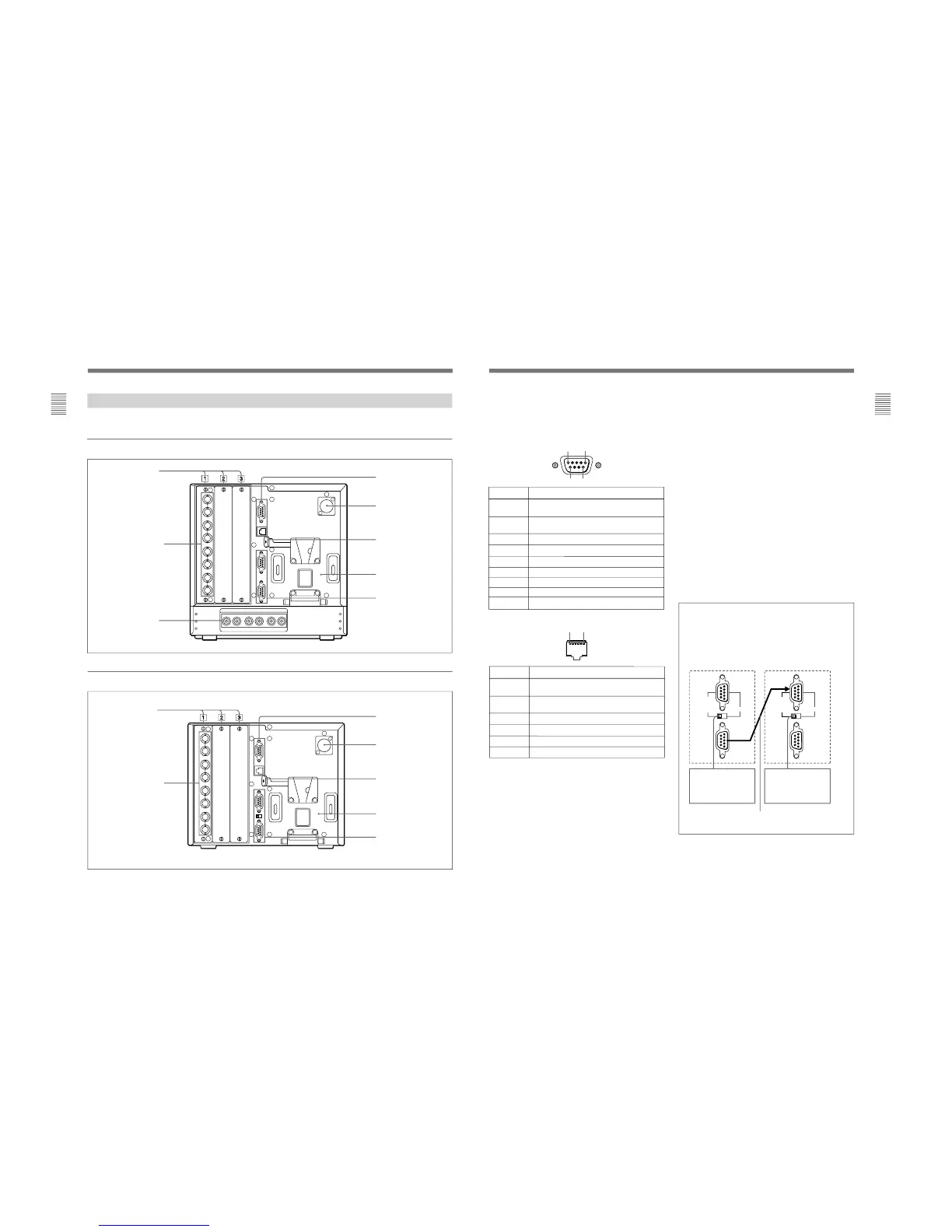
To switch each function between on and off or
between enable and disable, change pin connections in
the following way.
ON or enabled: Short each pin and pin 9 together for
D-sub 9-pin.
Short each pin and pin 5 together for modular
connector.
OFF or disabled: Leave each pin open.
Pin number
1
Set input signal channel 1 (numeric keypad
function)
2
Set input signal channel 2 (numeric keypad
function)
3 Set red tally lamp on or off
4 Set green tally lamp on or off
5 Select sync signal (SYNC button function)
6 Set underscan on or off
7 Set a 16:9 aspect ratio on or off
8
Functions
Set the 4:3 area marker display on or off
9
GND
Pin number
1
Set input signal channel 1 (numeric keypad
function)
2
Set input signal channel 2 (numeric keypad
function)
3 Set red tally lamp on or off
4 Set green tally lamp on or off
5 GND
6 Set underscan on or off
Functions
2 DC 12V IN jack (XLR-type, 4-pin)
Connects the DC 12V external power source to use the
monitor.
3 EJECT button
While sliding this button, remove the AC adaptor or
battery.
4 AC adaptor/battery attachment place
Attach the AC adaptor or battery.
5 SERIAL REMOTE connectors (female, D-sub 9-
pin), and SERIAL REMOTE/CTRL UNIT select
switch (BVM-D9H1U/D9H1E/D9H1A only)
These are RS-485 serial interface connectors, used for
connecting two or more BVM-xxE/F/G, BVM-xxD
and HDM-xxE series monitors. The IN and OUT
connectors form a loop-through connection.
BVM-D9H1U/D9H1E/D9H1A only: The SERIAL
REMOTE/CTRL UNIT select switch is set to SERIAL
REMOTE at the factory.
(continued)
For connecting the monitor (used for daisy
chain connections)
Connect two monitors using a cable with D-sub 9-
pin plugs such as an RCC-5G (not supplied) as
follows:
 Loading...


