4-3
BVM-D9H1U/D9H5U/D9H1E/D9H5E/D9H1A/D9H5A
High Voltage Hold-Down Check
When the following parts (the parts to which the mark is
attached on the schematic diagram) are replaced, be sure to
perform the following checks.
P board ........ IC509, IC511, D527, R539, R577, R578,
R579, R580, R592, R588, R587
1. Turn off the main power.
2. Connect a digital voltmeter between TP505 and TP514
(GND) of P board.
3. Connect a 200 kΩ variable resistor between TP508
and TP514 (GND) of P board.
[Adjust the 200 kΩ variable resistor to its maximum
resistance value.]
4. Turn on the main power.
5. Connect the 480/60i all black signal (see note) to input
connector.
Note: NTSC all black signal
6. Push the BRIGHTNESS and CONTRAST buttons to
their MANUAL positions (to turn the green LEDs on
the buttons.)
7. Set the BRIGHTNESS and CONTRAST buttons to
their MIN positions.
8. Confirm that the raster disappears from the CRT
screen when the DC voltage at TP505 reaches the
following voltage as the 200 kΩ variable resistor is
turned to decrease its resistance value gradually.
4.90 to 5.10 V
9. Turn off the main power.
10. Remove the 200 kΩ variable resistor from TP508.
11. Turn on the main power.
12. Confirm that the DC voltage at TP505 is as follows.
3.95 ± 0.15 V
13. Connect the 480/60i entire white signal to input connector.
14. Set the BRIGHTNESS and CONTRAST buttons to
their MAXIMUM positions.
15. Confirm that the DC voltage at TP505 is as follows.
4.25 ± 0.20 V
16. Disconnect the digital voltmeter.
[Connection]
P board (Side A)
ABC
1
2
3
4
5
6
Digital
voltmeter
200kΩ
TP508
TP505
TP514
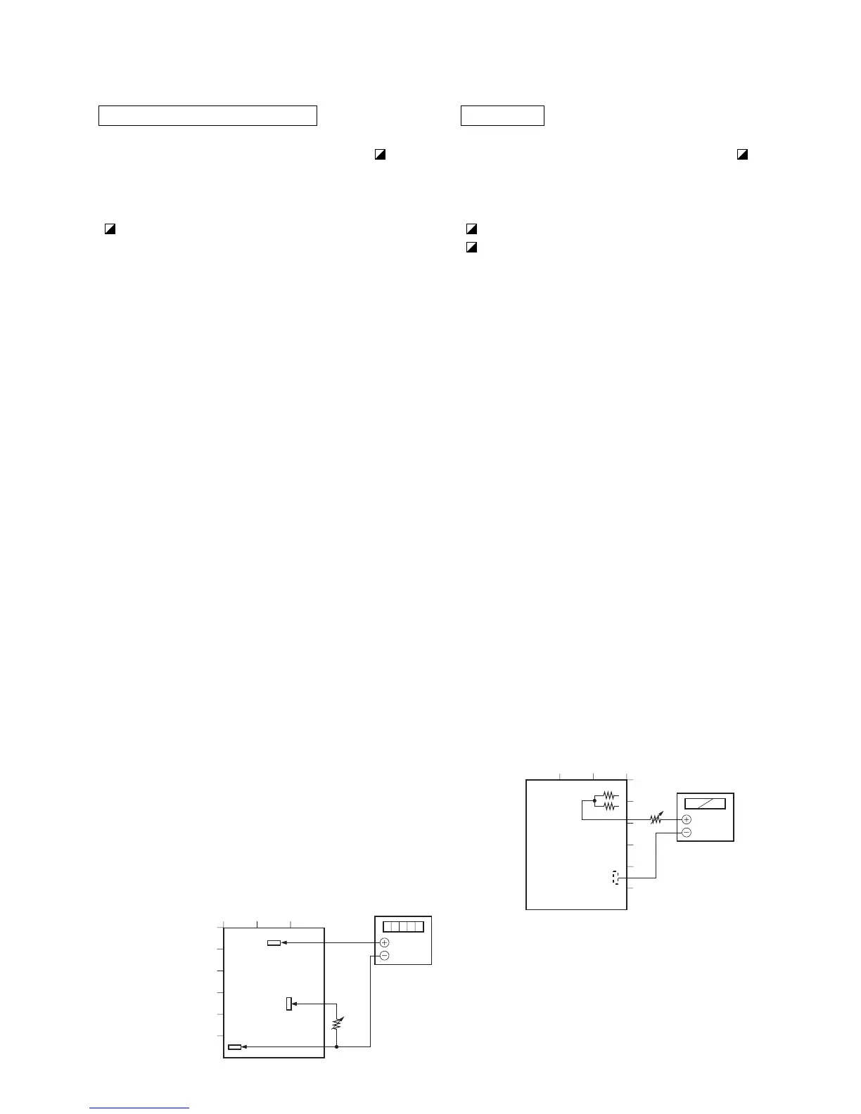
ABL Check
When the following parts (the parts to which the mark is
attached on the schematic diagram) are replaced, be sure to
perform the following checks.
P board ........ R1507, R1508, R1509
B board........ R1461, R1464, R1467, R1469, R1470,
R1471
1. Turn off the main power.
2. Disconnect the CN504 connector from the P board.
3. Connect a DC ammeter between pin-1 and pin-3 of
CN504 on the P board
[Pin-3 is the positive (+) side.]
4. Turn on the main power.
5. Connect the 1080/60i all white signal (see note) to
input connector.
Note: 1125 (1080) entire white signal
6. Push the BRIGHTNESS and CONTRAST buttons to
their MANUAL positions (to turn the green LEDs on
the buttons.)
7. Check to see that ABL operates when the BRIGHT-
NESS and CONTRAST buttons are turned from their
MIN positions toward the MAX positions. [Check
that the maximum value of the DC ammeter reading is
within the range as shown below.]
0.50 to 0.60 mA
8. Turn off the main power.
9. Disconnect the DC ammeter.
10. Connect CN504 connector to the P board again.
[Connection]
P board (Side B)
1
2
3
4
5
6
CBA
50kΩ
R1505
R1504
TP503
Ammeter
 Loading...


