3-4
BVM-D9H1U/D9H5U/D9H1E/D9H5E/D9H1A/D9H5A
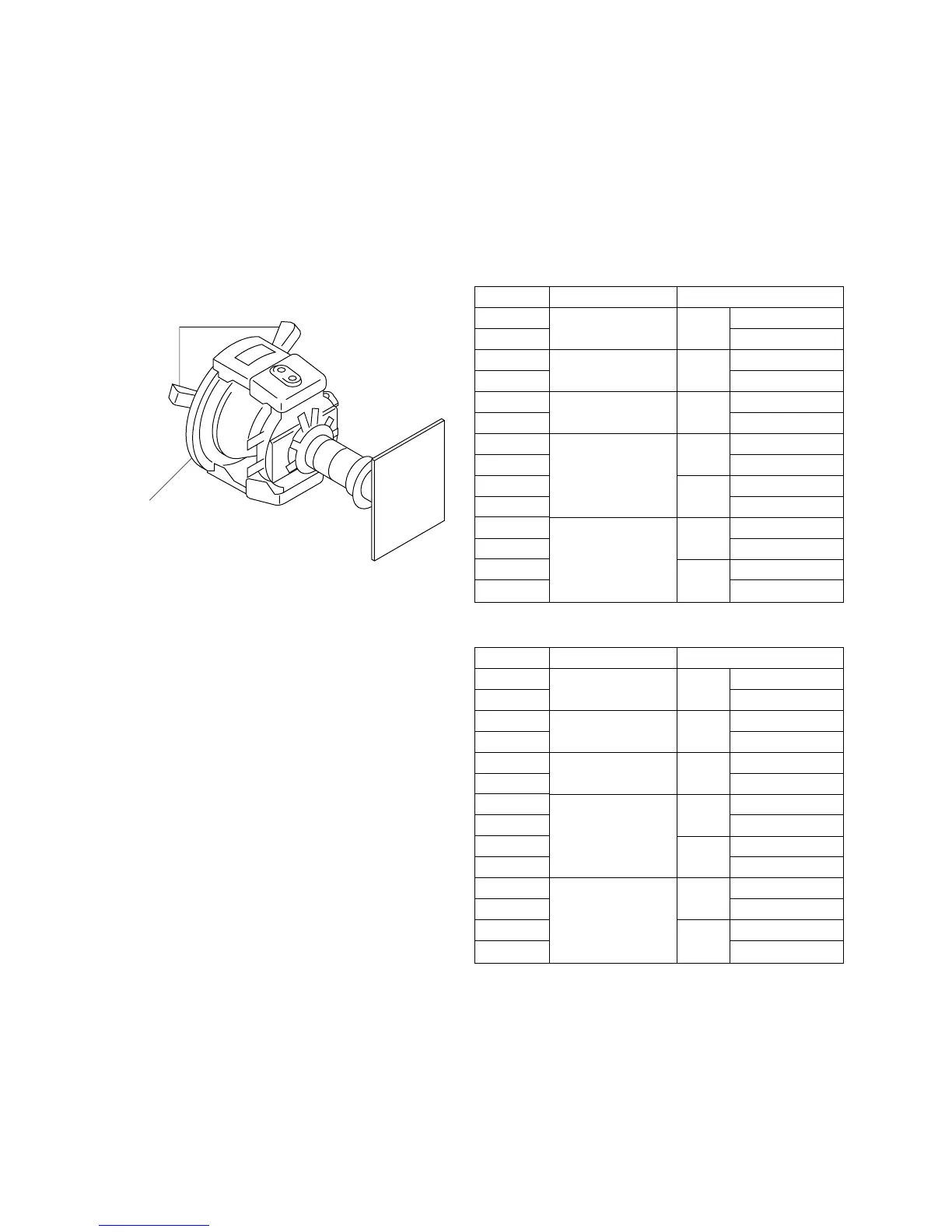
Deflection yoke (DY)
DY spacers
10. Connect the 480/60i cross-hatch signal (see note) to
the ANALOG Y/G input connector.
Note: This is the NTSC cross-hatch signal.
11. Adjust the DY inclination. After DY inclination
adjustment is complete, tighten the DY fixing screw.
12. Fix the deflection yoke (DY) using the three DY
spacers.
Fig. 1-4
..
..
. Final adjustment
When the adjustment is complete, check that mis-landing
(landing error) does not occur even when the monitor is
directed in all directions of east, west, south and north.
Mode
MODE1
MODE2
MODE3
MODE4
MODE5
MODE6
MODE7
MODE8
MODE9
MODE10
MODE11
MODE12
MODE13
MODE14
Signal format
1080/60i 16 : 9
(1125)
1035/60i 16 : 9
(1125)
720/60p 16 : 9
480/60p 16 : 9
(525)
4 : 3
480/60i 16 : 9
(525)
4 : 3
Screen mode
NORMAL
UNDER SCAN
NORMAL
UNDER SCAN
NORMAL
UNDER SCAN
NORMAL
UNDER SCAN
NORMAL
UNDER SCAN
NORMAL
UNDER SCAN
NORMAL
UNDER SCAN
Mode
MODE15
MODE16
MODE17
MODE18
MODE19
MODE20
MODE21
MODE22
MODE23
MODE24
MODE25
MODE26
MODE27
MODE28
Signal format
1080/48i 16 : 9
(1125)
1080/50i 16 : 9
(1125)
720/50p 16 : 9
575/50P 16 : 9
(625)
4 : 3
575/50i 16 : 9
(625)
4 : 3
Screen mode
NORMAL
UNDER SCAN
NORMAL
UNDER SCAN
NORMAL
UNDER SCAN
NORMAL
UNDER SCAN
NORMAL
UNDER SCAN
NORMAL
UNDER SCAN
NORMAL
UNDER SCAN
[H. Blanking Adjustment]
..
..
. Preparation
1. Connect the monoscope signal of the signal formats
that are shown in the following table, to the ANALOG
Y/G input connector. Perform the H. blanking adjust-
ment in the respective screen modes using the respec-
tive signal formats.
60 Hz system
50 Hz system
2. Increase the brightness by adjusting the BRIGHT
control so that blanking becomes visible on screen.
Note: The following adjustment menus are located in
the directory under the DEFLECTION menu of the
MAINTENANCE menu.
H BLK LEFT H CENT
H BLK RIGHT H PHASE
H SIZE
 Loading...


