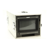
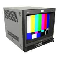
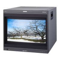
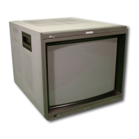
4-1
BVM-D9H1U/D9H5U/D9H1E/D9H5E/D9H1A/D9H5A
Section 4
Safety Related Adjustments
This section describes the adjustment procedure that is
required when the safety related parts are replaced.
[Preparation]
..
..
. Required tools and measuring equipment
1. Signal generator
YPBYPR signal generator
..
..
. 1080/60i (1125) : SMPTE274M standard
..
..
. 480/60i (525) : ITU601 (Refer to page 1-29)
2. Electrostatic voltmeter: Singer ESH-27X or ESH-23X
or equivalent
3. Digital voltmeter
4. 200 kΩ variable resistor
5. 50 kΩ variable resistor
6. Ammeter
. Set the INPUT CONFIGURATION menu
Set the INPUT CONFIGURATION menu of the SETUP
menu as shown below unless otherwise specified.
FORMAT................................ YPBPR
SLOT NO................................ 1
INPUT NO.............................. 1
SYNC MODE ......................... INT
APEARTURE VALUE .......... 100
CHANNEL NAME ................ PROG
COLOR TEMP ....................... STD
H PHASE ................................ 000
MARKER PHASE.................. 000
MARKER WIDTH ................. 000
SLOT No. 1
Component signal generator
Y/G terminal
P
B
/B terminal
P
R
/R terminal
SYNC terminal
BKM-129X (BX Board)
BVM-D9H1U/D9H5U/D9H1E/D9H5E/D9H1A/D9H5A
 Loading...


