5-1
BVM-D9H1U/D9H5U/D9H1E/D9H5E/D9H1A/D9H5A
Section 5
Circuit Adjustments
5-1. B Board Adjustments
This section describes the following adjustments that are
required when the parts are replaced or maintenance is
performed in the B board.
1. RGB signal adjustment
2. 15k YPBPR SMPTE (709) signal adjustment
3. 15k YPBPR SMPTE (601) signal adjustment
4. 15k YPBPR BETACAM SETUP 0 (601) signal
adjustment
5. 15k YPBPR BETACAM SETUP 7.5 (601) signal
adjustment
6. 33k YPBPR SMPTE (709) Signal Adjustment
Control Settings
..
..
. Set the INPUT CONFIGURATION menu of the SETUP
menu as shown below.
FRMAT ............... YPBPR
SLOT NO ............ 1
INPUT NO .......... 1
. Set “128” to the CHROMA data using the CHROMA
control knob.
. Perform the following operaion using the SYSTEM
CONFIG menu.
Select the B BOARD using the RE-LOAD FACTORY
DATA of the SYSTEM menu.
Equipment Required
Name Main Specifications Model Name
Signal generator 15 kHz/60 Hz RGB VG-854 or equivalent
15 kHz/60 Hz YPBPR SMPTE (709)
15 kHz/60 Hz YPBPR SMPTE (601)
15 kHz/60 Hz YPBPR BETACAM SETUP 7.5 (601)
33 kHz/60 Hz YPBPR SMPTE (709)
Oscilloscope Frequency: DC to 150 MHz or more TEKTORONIX 2445A
Dual trace or equivalent
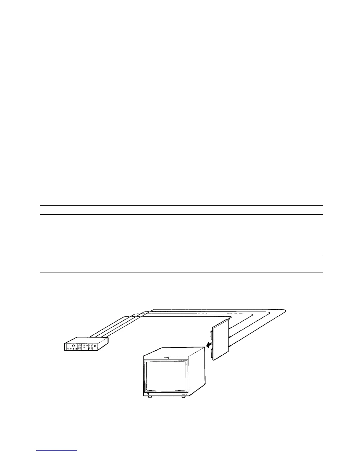
Connection (1)
SLOT No. 1
Component signal generator
Y/G terminal
P
B
/B terminal
P
R
/R terminal
SYNC terminal
BKM-129X (BX board)
BVM-D9H1U/D9H5U/D9H1E/D9H5E/D9H1A/D9H5A
 Loading...


