Series 4180 Powerhead32
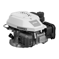
N Lift the lever (6) slightly, pull the contact spring (5) out
of the guide (arrow) and push it to one side.
N Remove the lever (6).
N Remove the yellow ground wire (15) together with the
contact spring (5).
N Pull the contact spring (5) off the yellow ground wire
(17).
N Remove the black short-circuit wire (17) together with
the contact spring (4).
N Pull the contact spring (4) off the black short-circuit
wire (17).
N Remove short-circuit wire, ground wire and throttle
cable from the engine, @ 8.8.
12.5 Assembling the Control Handle
N Push blade receptacle of black short-circuit wire (17)
onto the contact spring (4) so that its open side faces
the throttle trigger (11).
N Fit the black short-circuit wire (17) together with the
contact spring (4) in the guides in the handle housing.
N Fit the lever (6).
N Push blade receptacle of yellow ground wire (15) onto
the contact spring (5) so that its open side faces the
throttle trigger (11).
N Push the yellow ground wire (15) with contact spring
(5) in the guides in the handle housing, and fit the
contact spring (5) in the recesses in the lever (5).
N Depress lever (6) and check that the contact springs
(4, 5) make contact.
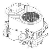
N Fit the torsion spring (7) on the pivot pin so that its
downward angled leg locates against the rib (arrow).
N Turn the upper leg (arrow) of the torsion spring
counterclockwise and locate it against the housing
(arrow)
N Push the lockout lever (8) onto the pivot pin (arrow)
so that it fits past the upper leg of the torsion spring
(7).
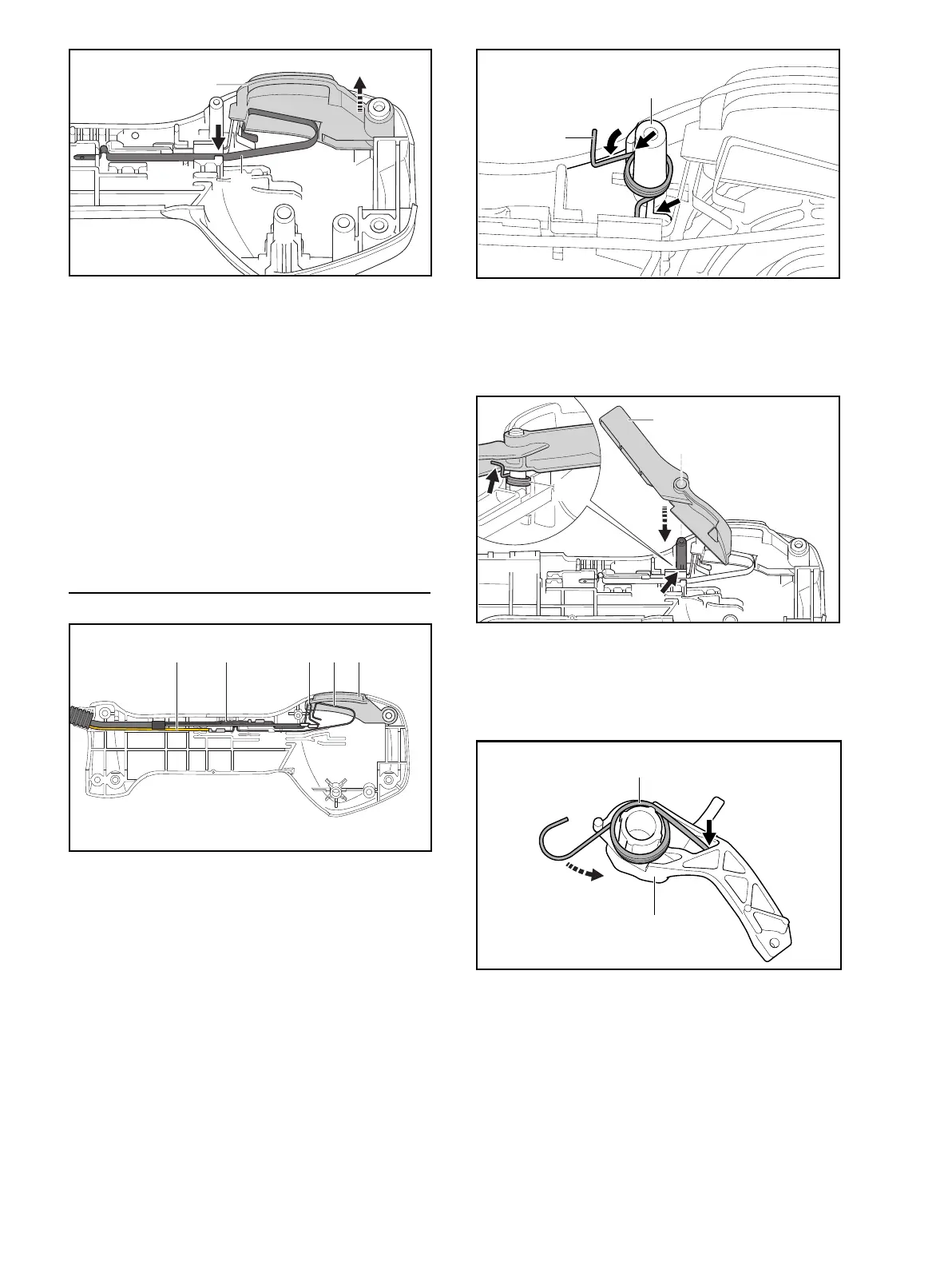
N Hook the torsion spring (7) (arrow) to the lockout
lever (8) and fit the lockout lever (8) in position.
N Push the straight leg of torsion spring (10) into the
opening (arrow).
N Tension the hooked leg (10) counterclockwise and fit
it behind the stop.
5
6
0000-GXX-1931-A0
1715 4 65
0000-GXX-2473-A0
7
8
0000-GXX-2475-A0
 Loading...