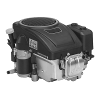
Series 4180 Powerhead40
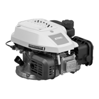
N Fit the cam gear (7) so that the arrows on it line up
with the marks (arrows) in the cylinder.
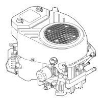
N Fit the pin (6) in the cam gear’s bore.
N Fit the pin (6).
N Fit the left cam follower (4) first, then the right cam
follower (5).
N Apply Dirko sealant to groove in cover (8).
N Fit the cover (8).
N Insert and tighten down the screws (9).
N Install rocker arm, pushrod, @ 15.2.
N Fit the starter cup (11) and tighten down the nut (10).
15.3 Checking / Adjusting Valve Clearance
If engine is low on power or cranking effort is very high,
check valve clearance.
Setting engine to top dead center on power stroke
When the mark on the flywheel is in line with the right-
hand screw on the ignition module, the setting is either
TDC on power stroke or TDC on valve overlap.
The engine must be set to TDC on power stroke to check
and adjust valve clearance.
Check or adjust valve clearance only when the engine is
cold.
N Remove the cover, @ 4.2.
N Take out the screw (20) and remove together with
sealing ring (19), valve cover (18) and gasket (17).
N Pull boot off the spark plug.
N Unscrew the spark plug.
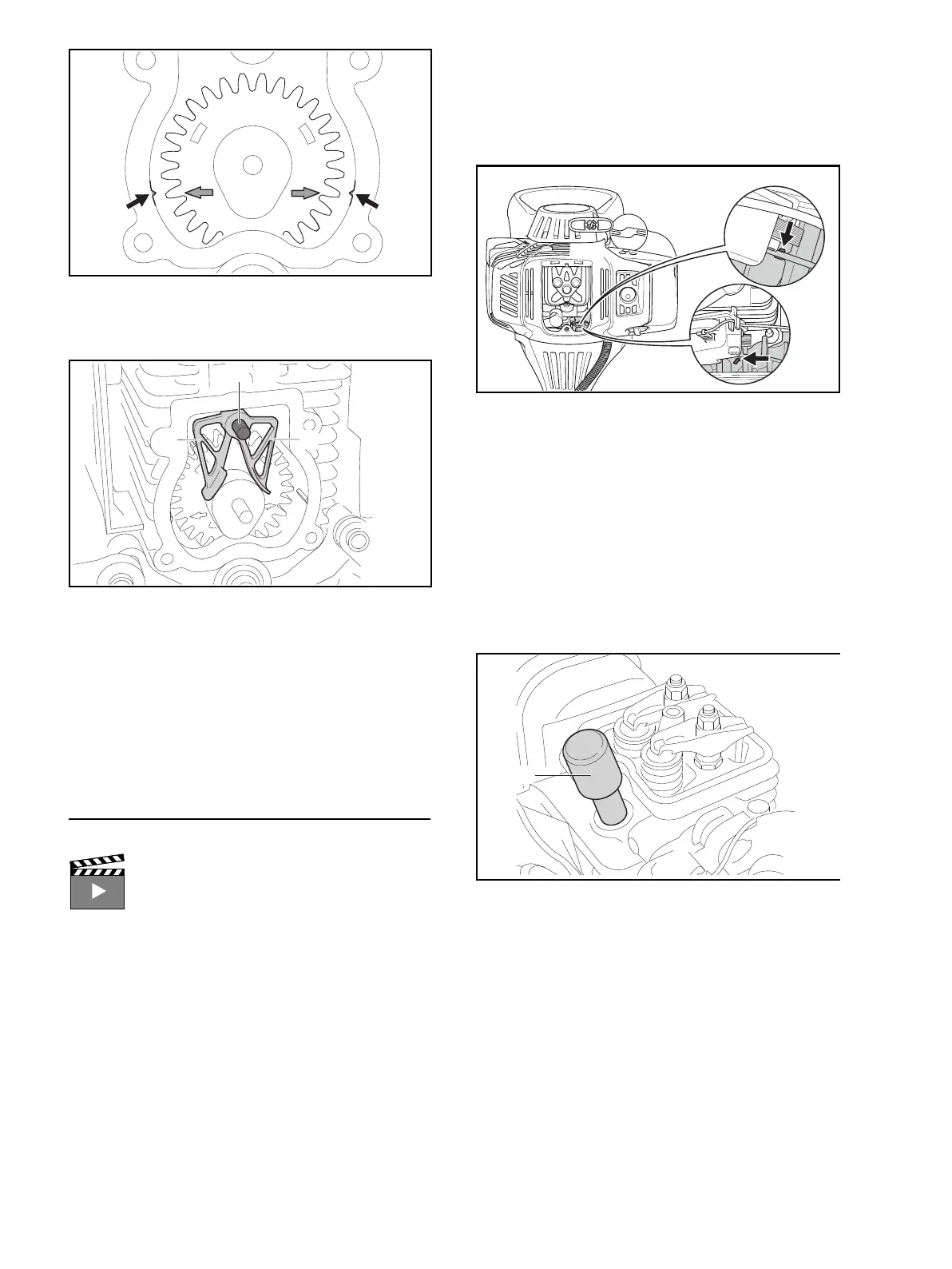
N Rotate the crankshaft until the mark (arrow) on the
flywheel or the on the front of the flywheel (arrow) is
in line with the right-hand screw on the ignition
module (top dead center).
Observe the two rocker arms while rotating the flywheel
up to the mark. The valves must not be operated, the
rocker arms must move freely (TDC on power stroke).
If the valves are operated and the rocker arms cannot be
moved, carry out the following steps to obtain TDC on the
power stroke:
N Remove the shroud, @ 4.2.
N Remove the rewind starter, @ 5.1.
N Fit the locking screw 4282 890 2700 (25).
N Turn the crankshaft counterclockwise until the piston
butts against the locking screw (25).
N Unscrew the nut (10) and remove it together with the
starter cup (11).
N Remove the locking screw 4282 890 2700 (25).
N Take out the screws (9).
N Pry off the cover (8) at the recesses.
Interactive video “Adjusting Valve Clearance”
0000-GXX-1941-A0
 Loading...