Series 4180 Powerhead38
15.1 Tools, Servicing Aids
– Socket, T27x125 – 0812 542 2104
– Setting gauge – 4180 893 6400
– Locking screw – 4282 890 2700
– Torque wrench – 5910 890 0302
– Torque wrench – 5910 890 0312
– Screwdriver, T27x200 – 5910 890 2415
– Screwdriver, Q-SW 8x200 – 5910 890 2420
– Socket, 13 mm, long – 5910 893 2804
– Dirko HT red sealant – 0783 830 2000
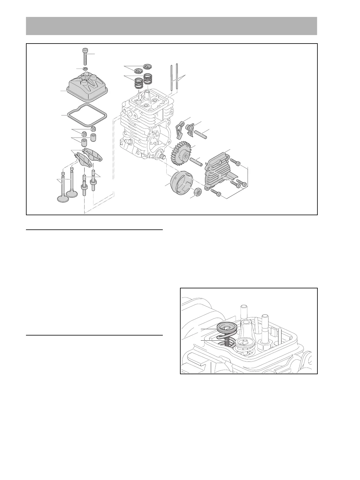
15.2 Disassembling / Assembling Valve Gear
Removing rocker arm, pushrod
N Remove the shroud, @ 4.2.
N Clean area around valve cover (18).
N Take out the screw (20) and remove together with
sealing ring (19), valve cover (18) and gasket (17).
N Unscrew and remove the nut (16).
N Remove the sleeve (15).
N Remove the rocker arm (14).
N Take out the pushrod (3).
Installing rocker arm, pushrod
N Fit the pushrod (3).
N Fit the rocker arm (14).
N Fit the sleeve (15).
N Screw nut (16) onto the collar screw (12).
N Adjust valve clearance, @ 15.3.
N Fit gasket (17) in the valve cover (18).
N Place valve cover (18) in position, fit screw (2) with
new sealing ring (19) and tighten down.
Removing the valves
N Remove rocker arm and pushrod, @ 15.2.
N Remove the crankshaft, @ 16.9.
N Press the valve spring retainer (1) down and move it
sideways until the valve stem is in the large hole.
N Remove the spring retainer (1) and valve spring (2).
N Pull the valve (13) out of the cylinder.
15 Valve Gear
7
6
8
4
3
20 M5x30 (5 Nm / 44 lbf. in.)
19
18
17
16
14
11
10 M8x1 (17 Nm / 150 lbf. in.)
5
6
13
15
1
2
9 D4x18 (4,5 Nm / 40 lbf. in.)
12
M5x16
(9 Nm / 80 lbf. in.)
0000-GXX-1935-A0
1
13
0000-GXX-2361-A0
 Loading...