Series 4180 Powerhead34
13.1 Special Servicing Tools, Servicing Aids
– Socket, T27 – 0812 542 2104
– Torque wrench – 5910 890 0302
– Screwdriver, T20 – 5910 890 2301
– Screwdriver, T27x200 – 5910 890 2415
– Punch-down tool – 5910 890 4000
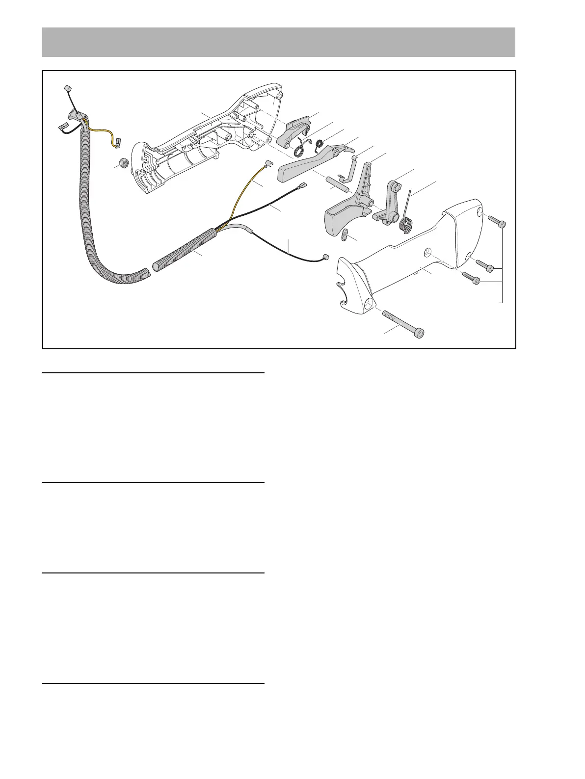
13.2 Removing the Control Handle
N Unscrew the screw (1) and remove it with the
nut (15).
N Pull the control handle off the bike handle.
N Pull the hose off the retainers.
13.3 Fitting the Control Handle
N Push the control handle onto the bike handle so that
the throttle trigger faces the gearbox.
N Insert the screw (1) with nut (15) and tighten it down
firmly.
N Push the protective hose into the retainer so that it
remains straight.
13.4 Disassembling the Control Handle
N Remove the control handle, @ 13.2.
N Take out the screws (10).
N Remove ‘outer handle molding’ (16).
N Remove the torsion spring (9).
N Take out the throttle trigger (7) together with the lever
(8).
N Unhook the throttle cable (23).
N Remove the lockout lever (5) and torsion spring (4).
N Remove the torsion spring (4).
N Pull out the lever (2).
N Disconnect ground wire (23) and pull ground wire out
of the ‘inner handle molding’ (1).
N Pull the contact spring (6) together with the short
circuit wire out of the ‘inner handle molding’ (1).
N Pull the contact spring (6) off the short circuit wire.
N Remove short circuit wire, ground wire and throttle
cable from the engine, @ 8.8.
13 Control Handle – Bicycle Handle
2
15
13
4
3
5
14
1
12
22
23
21
6
7
8
9
16
P4x16 (1,3 Nm / 12 lbf. in.) 10
0000-GXX-2408-A0
M5x48x22 (2,5 Nm / 22 lbf. in.) 11
 Loading...