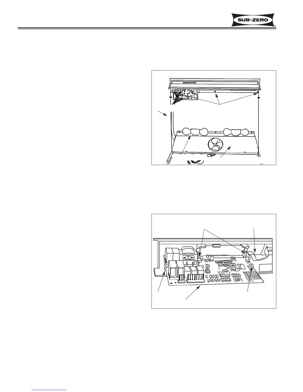
Figure 7-21. Upper Refrigerator Compartment Area
Figure 7-22. Control Board Removal
Control Board
Panel Mounting Screws
Control Panel
Evaporator Fan Shroud
Control Board
Tab
Tab
Ribbon Cable
Forward Tabs
Component Access / Removal
600 Series
(Prior to #1810000)
7-10
#3756270 - Revision B - January, 2006
REFRIGERATOR MECHANICAL AND ELEC-
TRICAL COMPONENTS
Control Board (Models 601R, 611, 632, 642, 650)
NOTE: Model 690 control board access and removal is
covered later in this section.
The control board is held in position by two sets of tabs
behind the left side of the control panel. The two for-
ward tabs position the LCD in the control panel window,
while the other two tabs secure the middle of the control
board. The control board is then shielded by a control
enclosure, and concealed by the light diffuser.
To access and remove the control board, the light dif-
fuser must first be removed. Now extract the screws
securing the control enclosure to the ceiling of the com-
partment. Then, lower the back of the enclosure while
pulling it toward the rear of the unit. Disconnect all
electrical leads attached to the control board, including
the membrane switch ribbon cable. Expand the two
tabs at the middle of the control board outward while
pulling the back of the board down slightly. Then,
expand the two forward tabs outward that hold the LCD
in position, and pull the control board down and toward
the rear of the unit. (See Figures 7-21 & 7-22)
Control Panel (Models 601R, 611, 632, 642, 650)
NOTE: Model 690 vertical control panel access and
removal is covered later in this section.
The control panel, which houses the membrane switch,
is secured to the ceiling of the compartment by two
rows of screws. The front row of screws are through
keyhole slots in the assembly. To access and remove
the control panel, the light diffuser and control enclo-
sure must be removed first.
NOTE: It is recommended, but not necessary, to
remove the control board in order to remove the control
panel. If leaving the control board secured to the con-
trol panel, all electrical leads attached to the control
board must be disconnected.
Now, extract the back row of screws at the back of the
control panel. Push the panel back to release it from
the front row of screws, then lower the panel down and
pull out. (See Figure 7-21)
 Loading...


