Component Access / Removal
600 Series
(Prior to #1810000)
7-32
#3756270 - Revision B - January, 2006
LOWER COMPRESSOR AREA
MECHANICAL AND ELECTRICAL
COMPONENTS
This section covers the Models 601R and 601F,
explaining how to access and remove mechanical and
electrical components in the lower compressor area.
This will include access and removal of the light and fan
switches, water valve and condenser fan motor.
Light and Fan Switch (Models 601R, 601F)
The light and fan switches are mounted to the top sec-
tion of the unit grille. To access and remove the light
and/or fan switches, the lower section of unit grille will
need to be removed first. Now, open cabinet door and
extract the screws at the top left and right corners. Pull
upper grille assembly forward slightly and disconnect
the electrical leads from the switch being removed.
Depress the tabs on each side of the switch while push-
ing the switch out of the opening in the grille top sec-
tion. (See Figure 7-60)
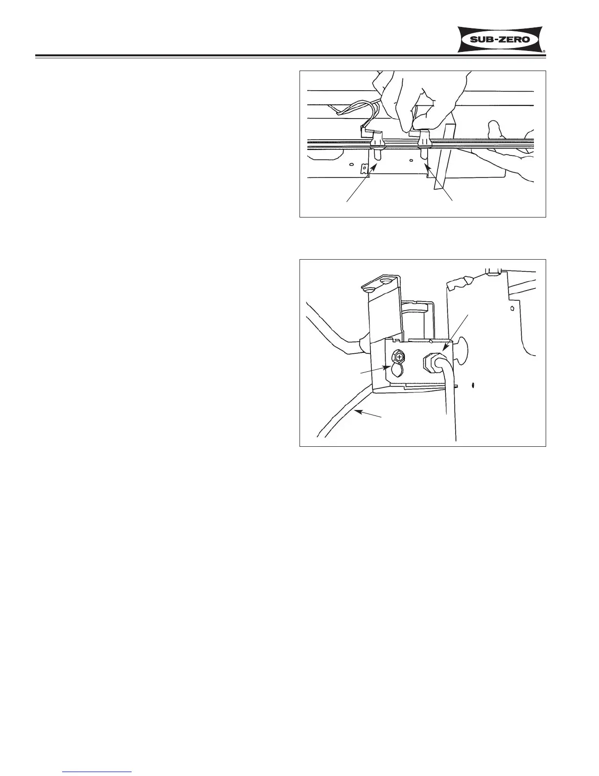
Water Valve (Model 601F)
NOTE: To avoid water damage, shut off water supply to
unit before attempting to remove water valve.
NOTE: To access the water valve it is recommended,
but not necessary, to remove the top section of the unit
grille assembly after removing the bottom section.
The water valve is mounted to a bracket at the right
hand side of the compressor area. To access and
remove the water valve, first remove the lower section
of the unit grille. (See note above.) Now disconnect
the water inlet compression fitting. Loosen the mount-
ing screw which secures the valve to the bracket, and
push the bracket up until the screw head aligns with the
larger section of the keyhole slot. Push valve back until
the screw head clears the hole, then pull the valve out.
Disconnect the electrical leads from the solenoid, and
the plastic water line from the valve outlet. (See Figure
7-61)
Figure 7-60. Model 601F Light Fan & Switches
Light Switch Fan Switch
Figure 7-61. Model 601F Water Valve Removal
Inlet Fitting
Keyhole Slot
Plastic Water
Line
 Loading...


