Engine General Information and Diagnosis: 1A-104
DTC “C42” (P1650): IG Switch Circuit Malfunction
B817H21104025
Detected Condition and Possible Cause
Troubleshooting
NOTE
• Refer to “Ignition Switch Inspection in Section 9C (Page 9C-11)” for details.
• After repairing the trouble, clear the DTC using SDS tool. Refer to “Use of SDS Diagnosis Reset
Procedures (Page 1A-15)”.
DTC “C44” (P0130/P0135): HO2 Sensor (HO2S) Circuit Malfunction
B817H21104026
Detected Condition and Possible Cause
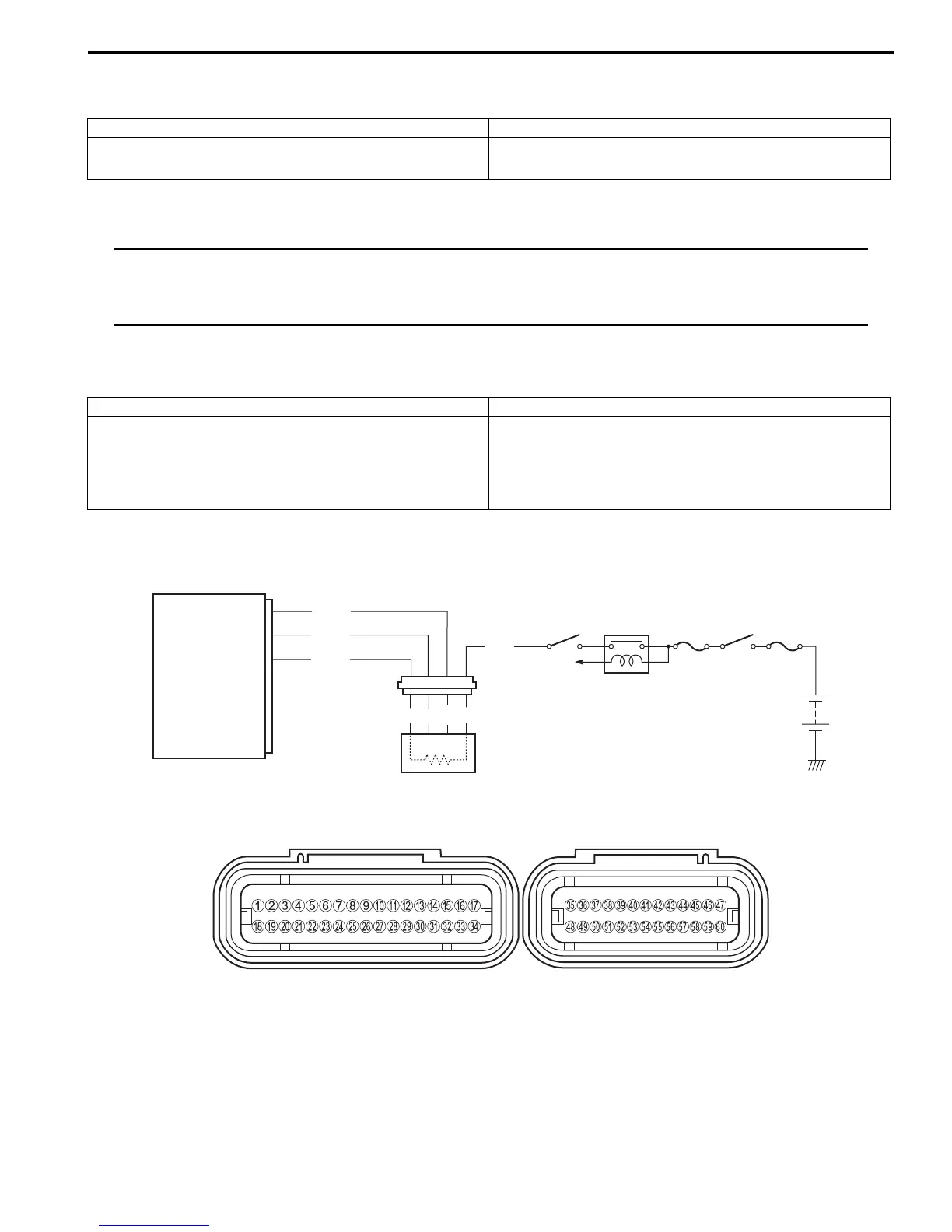
Wiring Diagram
ECM coupler (Harness side)
Detected Condition Possible Cause
Ignition switch signal is not input in the ECM. • Ignition system circuit open or short.
• ECM malfunction.
Detected Condition Possible Cause
HO2 sensor output voltage is not input to ECM during
engine operation and running condition.
Sensor voltage > 1.0 V
The heater can not operate so that heater operation
voltage is not supplied to the oxygen heater circuit.
• HO2 sensor circuit open or short.
• ECM malfunction.
• HO2 sensor lead wire/coupler connection.
• Battery voltage supply to the HO2 sensor
ECM
Side-stand
relay
Ignition
switch
Engine stop
switch
O/W
W
Gr
B
W
HO2 sensor
HO2
HO2.H
E2
To Side-
stand switch
B/Br
W/G
W/B
29
12
40
I718H1110114-04
I718H1110240-01

 Loading...