ABS: 4E-70
Front Wheel Speed Sensor Removal and
Installation
B817H24506002
CAUTION
!
• The ABS is made up of many precision
parts; never subject it to strong impacts or
allow it to become dirty or dusty.
• The wheel speed sensor cannot be
disassembled.
Removal
1) Turn the ignition switch OFF.
2) Remove the right frame head cover. (GSF650A/UA)
Refer to “Exterior Parts Removal and Installation
(GSF650/S/A/SAK7) in Section 9D (Page 9D-6)”.
3) Disconnect the front wheel speed sensor coupler (1).
4) Remove the front wheel speed sensor mounting
bolts.
5) Remove the front wheel speed sensor as shown in
the front wheel speed sensor routing diagram. Refer
to “Front Wheel Speed Sensor Routing Diagram
(Page 4E-9)”.
Installation
Refer to “Wheel Speed Sensor and Sensor Rotor
Inspection (Page 4E-73)”.
Install the front wheel speed sensor in the reverse order
of removal. Pay attention to the following points:
• Install the front wheel speed sensor as shown in the
front wheel speed sensor routing diagram. Refer to
“Front Wheel Speed Sensor Routing Diagram
(Page 4E-9)”.
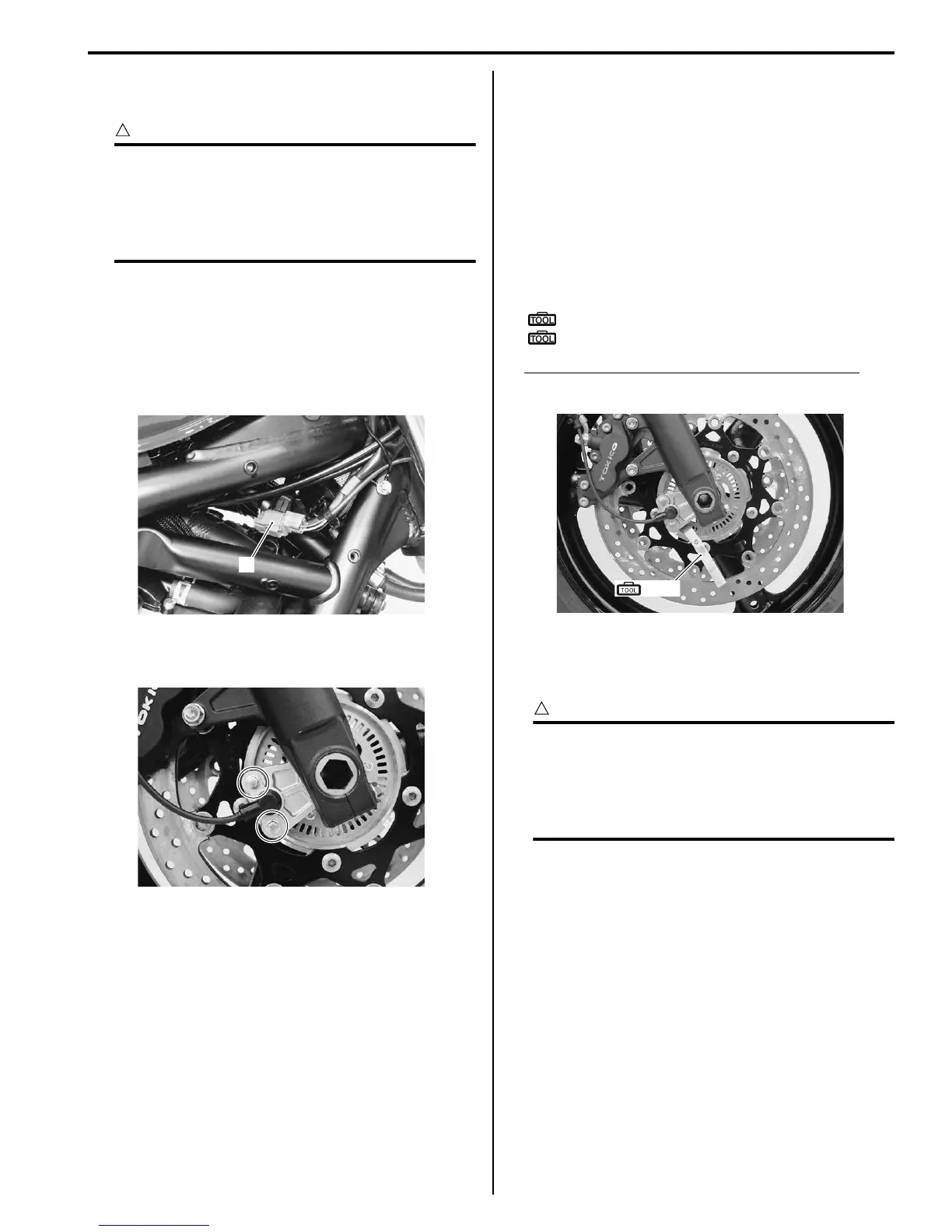
• Check the clearance between the front wheel speed
sensor and sensor rotor using the thickness gauge.
Special tool
(A): 09900–20803 (Thickness gauge)
(B): 09900–20806 (Thickness gauge)
Wheel speed sensor – sensor rotor clearance
0.3 – 1.5 mm (0.012 – 0.059 in)
Rear Wheel Speed Sensor Removal and
Installation
B817H24506003
CAUTION
!
• The ABS is made up of many precision
parts; never subject it to strong impacts or
allow it to become dirty or dusty.
• The wheel speed sensor cannot be
disassembled.
1
I718H1450100-01
I717H2450024-01
(A), (B)
I717H2450009-01

 Loading...