1I-7 Starting System:
Starter Relay Inspection
B817H21906006
Inspect the starter relay in the following procedures:
1) Remove the starter relay. Refer to “Starter Relay
Removal and Installation (Page 1I-6)”.
2) Apply 12 V to “A” and “B” terminals and check for
continuity between the positive and negative
terminals using the multi-circuit tester. If the starter
relay clicks and continuity is found, the relay is ok.
CAUTION
!
Do not apply battery voltage to the starter
relay for five seconds and more, since the
relay coil may overheat and get damaged.
Special tool
(A): 09900–25008 (Multi-circuit tester set)
Tester knob indication
Continuity test ( )
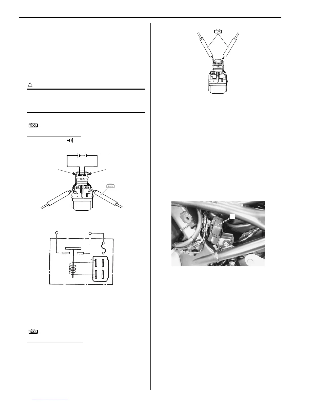
3) Measure the relay coil resistance between the
terminals using the multi-circuit tester. If the
resistance is not within the specified value, replace
the starter relay with a new one.
Special tool
(A): 09900–25008 (Multi-circuit tester set)
Starter relay resistance
3 – 6 Ω
4) Install the starter relay. Refer to “Starter Relay
Removal and Installation (Page 1I-6)”.
Turn Signal / Side-stand Relay Removal and
Installation
B817H21906007
Refer to “Electrical Components Location in Section 0A
(Page 0A-10)”.
Removal
1) Turn the ignition switch OFF position.
2) Remove the left frame cover. Refer to “Exterior Parts
Removal and Installation (GSF650/S/A/SAK7) in
Section 9D (Page 9D-6)”.
3) Remove the turn signal/side-stand relay (1).
Installation
Install the turn signal/side-stand relay in the reverse
order of removal.
“A” “B”
(A)
I649G1190021-04
“A”
“B”
-+
To batteryTo starter motor
I649G1190022-02
(A)
I649G1190023-03
1
I717H1190015-01