Wiring Systems: 9A-8
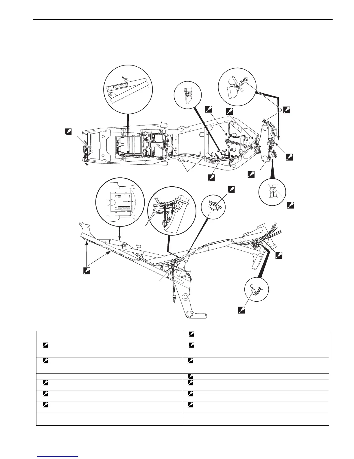
Wiring Harness Routing Diagram (GSF650/S/A/SAK7)
B817H29102003
7
5
1
4
“B”
“C”
“A”
2
6
3
“a”
“a” “a”
8
9
11
“D”
10
“E”
I717H1910907-03
1. Battery 10. Clamp
: Clamp the lead wire and brake hose (ABS) (GSF650A/SA).
2. Clamp (Except GSF650S/SA only)
: Pass through the speed meter lead right side of ignition switch.
11. Clamp
: Clamp the handle bar lead wires, ignition switch lead wire and front
wheel speed sensor lead wire (ABS) (GSF650A/SA).
3. Clamp (GSF650S/SA only)
: Clamp the handle switch right and left lead at the middle of blue
taping.
“A”: Pass through the horn and fan lead wire upper the brake hose (ABS)
(GSF650A/SA).
4. Clamp “B”: Pass through the lead wire under the water hoses.
5. Clamp
: Clamp tip backward.
“C”: Slack the lead wire downward.
6. Clamp
: Cut the tip of clamp after clamping.
“D”: Do not make slacked lead wire.
7. Wiring harness
: Be careful not to pinch the wiring harness with the frame and fender.
“E”: Set coupler vertically.
8. Brake hose (ABS). (GSF650A/SA only) “a”: 5 – 10 mm (0.2 – 0.4 in)
9. Rear wheel speed sensor (GSF650A/SA only)
 Loading...