Engine Mechanical: 1D-45
5) Cool down the new valve guides in a freezer for
about one hour and heat the cylinder head to 100 –
150 °C (212 – 302 °F) with a hot plate.
CAUTION
!
Do not use a burner to heat the valve guide
hole to prevent cylinder head distortion.
6) Apply engine oil to each valve guide and valve guide
hole.
7) Drive the guide into the guide hole using the valve
guide installer.
CAUTION
!
Failure to oil the valve guide hole before
driving the new guide into place may result in
a damaged guide or head.
Special tool
(A): 09916–43211 (Valve guide remover/
installer)
(D): 09916–43220 (Attachment)
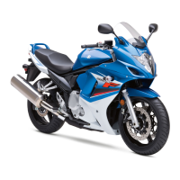
8) After installing the valve guides, refinish their guiding
bores using the reamer. Be sure to clean and oil the
guides after reaming.
Special tool
(C): 09916–34542 (Reamer handle)
(E): 09916–33210 (Valve guide reamer (4.5
mm))
NOTE
• Be sure to cool down the cylinder head to
ambient air temperature.
• Insert the reamer from the combustion
chamber and always turn the reamer
handle clockwise.
9) Reassemble the cylinder head. Refer to “Cylinder
Head Disassembly and Assembly (Page 1D-38)”.
10) Install the cylinder head assembly. Refer to “Engine
Top Side Assembly (Page 1D-26)”.
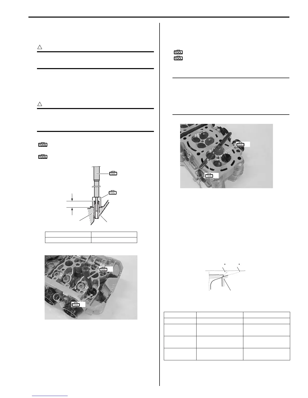
Valve Seat Repair
B817H21406030
The valve seats (1) for both the intake and exhaust
valves are machined to two different angles. The seat
contact surface is cut at 45°.
1. Cylinder head “a”: 15.0 mm (0.591 in)
2. Valve guide
“a”
(A)
(D)
1
2
I717H1140113-01
(A)
(D)
I718H1140128-01
Intake Exhaust
Seat angle 15°/45° 15°/45°
Seat width
0.9 – 1.1 mm
(0.035 – 0.043 in)
←
Valve
diameter
23 mm
(0.91 in)
20 mm
(0.79 in)
Valve guide
I.D.
4.500 – 4.512 mm
(0.1772 – 0.1776 in)
←
(E)
(C)
I718H1140129-01
1
45 15
IN. & EX.
I717H1140222-01
 Loading...