Engine Cooling System: 1F-3
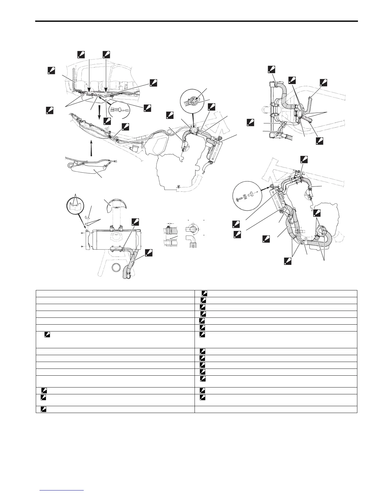
Water Hose Routing Diagram
B817H21602002
“C”
“O”
“Q”
“S”
“U ”
“T”
“P”
“R”
“F”
“C”
“D”
“D”
1
2
“G”
“J”
6
6
5
“N”
“B”
“a”
90 90
90
“A”
“C”
“D”
“L”
“K”
“H”
“I”
“C”
“C”
“E”
“D”
“D”
“F”
“J”
“M”
“F”
7
4
“D”
“M”
3
7
/
“V”
I717H1160002-02
1. Jiggle valve “I”: The clamp screw head should face left backward.
2. Thermostat “J”: The clamp screw head should face upward.
3. Reservoir tank “K”: The clamp screw head should face left upward.
4. Radiator heat shield “L”: The clamp screw head should face right side.
5. Radiator cover molding (GSF650 only) “M”: The clamp screw head should face left side.
6. Tape (GSF650 only) “N”: The clamp screw head should face forward.
7: Radiator outlet hose
: Check that there is at least 20 mm (0.8 in) of clearance between the
radiator outlet hose and the exhaust pipe.
“O”: Clamp the hose on yellow marking with the tail lamp harness.
“A”: Match mark “P”: Clamp the hose on white marking.
“B”: Marking position “Q”: Pass through the hose under the wiring harness.
“C”: White marking “R”: Pass through the hose under the seat lock plate.
“D”: Yellow marking “S”: Be careful not to pinch the hose between seat cushion and fender.
“E”: Red marking “T”: Pass through the hose between frame and reservoir tank. Be careful for
the hose not to be slackened.
“F”: The end of the clamp should face upward. “U”: Pass through the hose under the helmet holder.
“G”: The end of the clamp should face left side. “V”: Clamp the hose with the fan motor lead wire. Be careful not to insert the
coupler to the radiator heat shield hole.
“H”: The clamp screw head should face right backward. “a”: Clearance
 Loading...