4E-9 ABS:
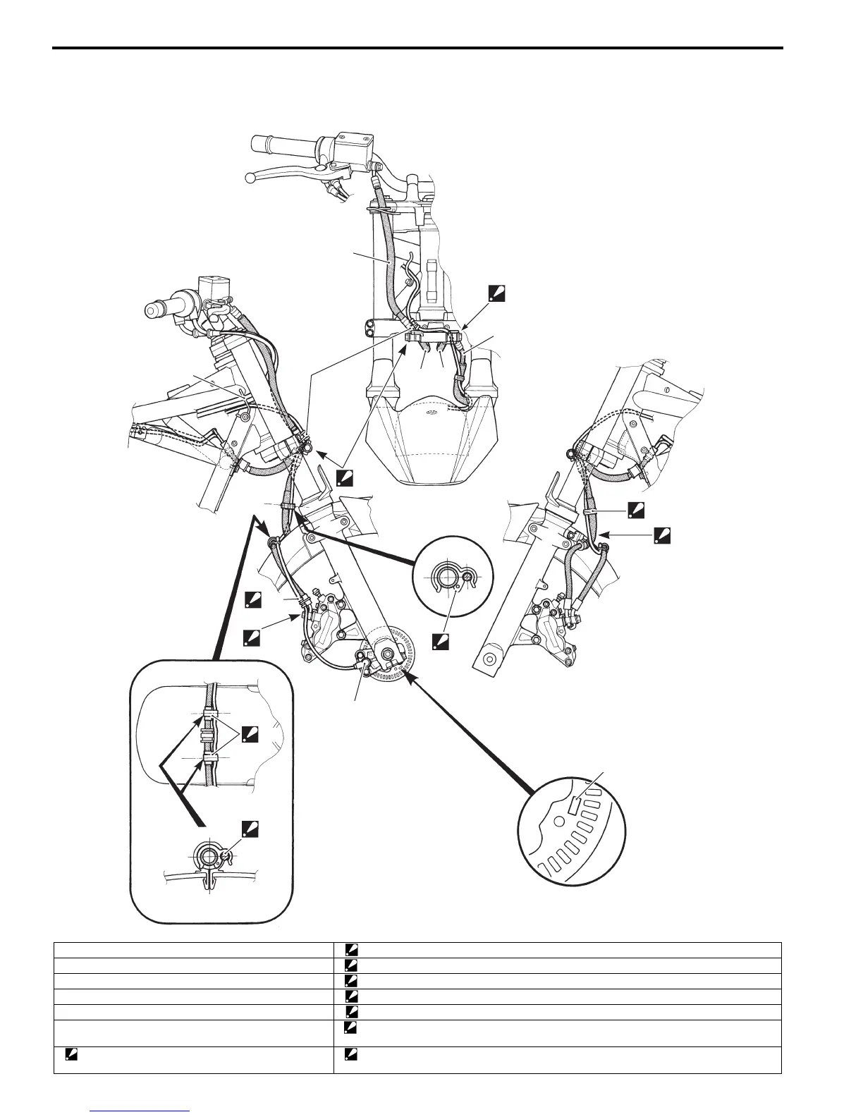
Front Wheel Speed Sensor Routing Diagram
B817H24502003
GSF650A/UA
3
6
“B”
5
4
“C”
1
2
“E”
“F”
“I”
“G”
“H”
8
7
“A”
“D”
I717H2450006-01
1. Clamp “B”: Pass through the sensor lead wire between brake hose No.2 and brake hose No.2 (L).
2. Guide “C”: Pass through the sensor lead wire in front of the brake hose.
3. Front brake hose No.1 “D”: Pass through the sensor lead wire outside of the brake hose.
4. Front brake hose No.1 (L) “E”: Clamp the sensor lead wire sleeve with the brake hose.
5. Front brake hose No.2 “F”: Pass through the sensor lead wire outside of the brake hose union bolt.
6. Front brake hose No.2 (L) “G”: Clamp the sensor lead wire at front side of the brake hose. Make clearance from the front
fender.
7: Clamp
: Clamp the sensor lead wire at the white marking.
“H”: Clamp the sensor lead wire on the protector of brake hose.

 Loading...