4E-13 ABS:
Diagnostic Information and Procedures
ABS Troubleshooting
B817H24504001
Many of the ABS malfunction diagnosing operations are
performed by checking the wiring continuity. Quick and
accurate detection of malfunctions within the complex
circuitry assures the proper operation of the ABS. Before
beginning any repairs, thoroughly read and understand
this Supplementary Service Manual.
The ABS is equipped with a self-diagnosis function. The
detected malfunction is stored as a diagnostic trouble
code which causes the ABS indicator light to light up or
flash in set patterns to indicate the malfunction.
Diagnostic trouble codes are stored even when the
ignition switch is turned to OFF and they can only be
erased manually. In order to repair the ABS correctly,
ask the customer for the exact circumstances under
which the malfunction occurred, then check the ABS
indicator light and the output diagnostic trouble codes.
Explain to the customer that depending on how the
motorcycle is operated (e.g., if the front wheel is off the
ground), the ABS indicator light may light up even
though the ABS is operating correctly.
Troubleshooting Procedure
Troubleshooting should be proceed as follows. If the
order is performed incorrectly or any part is omitted, an
error in misdiagnosis may result.
1) Gather information from the customer.
2) Perform the pre-diagnosis inspection. Refer to “Pre-
diagnosis Inspection (Page 4E-15)”.
3) Inspect the ABS indicator light. Refer to “ABS
Indicator Light Inspection (Page 4E-17)”.
4) Output the DTCs stored in the ABS control unit.
Refer to “DTC (Diagnostic Trouble Code) Output
(Page 4E-23)”.
5) Perform appropriate troubleshooting procedures
according to the DTCs output. Refer to “DTC Table
(Page 4E-33)”.
If troubleshooting procedures cannot be performed,
try to determine the cause of the malfunction
according to the information gathered in 1) through
4) and inspect the wiring. Refer to “ABS Wiring
Diagram (Page 4E-7)” and “ABS Unit Diagram
(Page 4E-8)”.
CAUTION
!
• When disconnecting couplers and turning
the ignition switch ON, disconnect the ABS
control unit coupler in order to prevent a
DTC from being stored.
• Each time a resistance is measured, the
ignition switch should be set to OFF.
6) Inspect the ABS components. Refer to “Wheel
Speed Sensor and Sensor Rotor Inspection
(Page 4E-73)”.
7) Delete the DTCs and check the brake operation.
Refer to “DTC (Diagnostic Trouble Code) Deleting
(Page 4E-26)”.
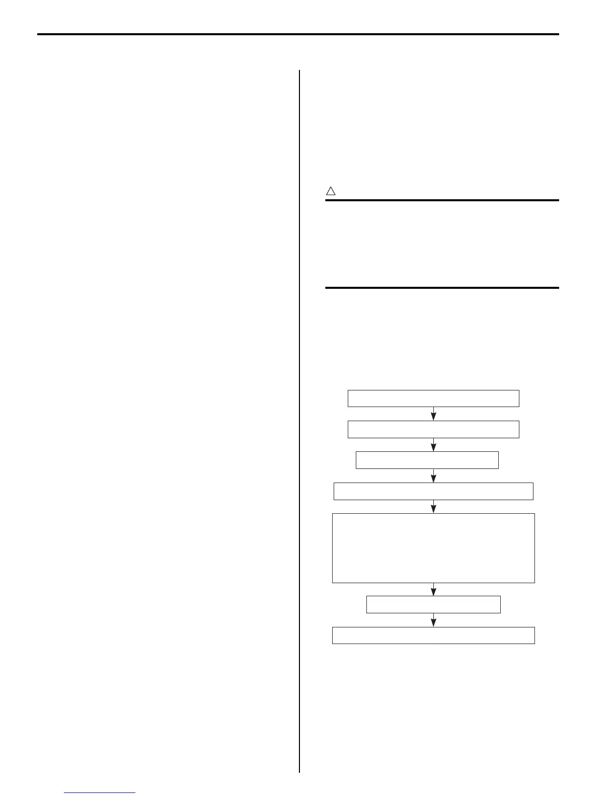
Basic Troubleshooting Diagram
1) Gather information from the customer.
2) Perform the pre-diagnosis inspection.
3) Inspect the ABS indicator light.
6) Inspect the ABS components.
4) Output the DTCs stored in the ABS control unit.
5) Perform appropriate troubleshooting procedures
according to the DTCs output.
If troubleshooting procedures cannot be per-
formed, try to determine the cause of the mal-
function according to the information gathered
in 1) through 4) and inspect the wiring.
7) Delete the DTCs and check the brake operation.
I718H1450120-01

 Loading...