1I-9 Starting System:
Diode inspection
1) Remove the turn signal/side-stand relay. Refer to
“Turn Signal / Side-stand Relay Removal and
Installation (Page 1I-7)”.
2) Measure the voltage between the “A”, “B” and “C”
terminals using the multi-circuit tester.
Special tool
: 09900–25008 (Multi-circuit tester set)
Tester knob indication
Diode test ( )
NOTE
If the multi circuit tester reads 1.4 V and
below when the tester probes are not
connected, replace its battery.
3) Install the turn signal/side-stand relay. Refer to “Turn
Signal / Side-stand Relay Removal and Installation
(Page 1I-7)”.
Gear Position Switch
1) Remove the left frame cover. Refer to “Exterior Parts
Removal and Installation (GSF650/S/A/SAK7) in
Section 9D (Page 9D-6)”.
2) Disconnect the gear position switch coupler (1).
CAUTION
!
When disconnecting and connecting the gear
position switch coupler, make sure to turn off
the ignition switch, or electronic parts may
get damaged.
3) Check the continuity between Blue and Black/White
lead wires with the transmission in “NEUTRAL”.
Special tool
: 09900–25008 (Multi-circuit tester set)
Tester knob indication
Continuity test ( )
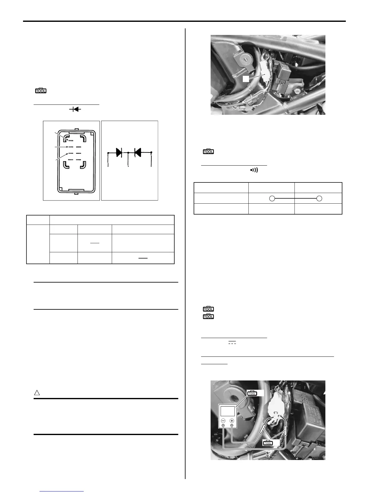
4) Connect the gear position switch coupler to the
wiring harness.
5) Insert the needle pointed probes to the lead wire
coupler.
6) Turn the ignition switch ON and side-stand to upright
position.
7) Measure the voltage between Pink and Black/White
lead wires using the multi-circuit tester when shifting
the gearshift lever from low to top.
Special tool
(A): 09900–25008 (Multi-circuit tester set)
(B): 09900–25009 (Needle pointed probe
set)
Tester knob indication
Voltage ( )
Gear position switch voltage (Except neutral
position)
0.6 V and more ((+) P – (–) B/W)
“A”
“B”“C” “A”
“B”
“C”
I649G1190029-02
+
Probe of tester to:
“A”
“A”“C”“B”,
“C”“B”,
–0.4 0.6 V
1.4 V and more
(Tester's battery voltage)
-
Probe of
tester to:
I649G1190046-04
1
I717H1190017-01
ON (Neutral)
OFF (Except neutral)
BI B/W
I649G1190045-03
V
(A)
(B)
I717H1190018-01

 Loading...