Multi Pro 1750
Page 5 − 28
Electrical System
Electrical System Quick Checks
Battery Test (Open Circuit Test)
Use a multimeter to measure the voltage between the
battery terminals.
Set the multimeter to the DC volts setting. The battery
should be at a temperature of 60
o
to 100
o
F (16
o
to 38
o
C). The ignition key should be in the OFF position and
all accessories turned off. Connect the positive (+) me-
ter lead to the positive battery post and the negative (−)
meter lead to the negative battery post.
NOTE: This test provides a relative condition of the bat-
tery. Load testing of the battery will provide additional
and more accurate information.
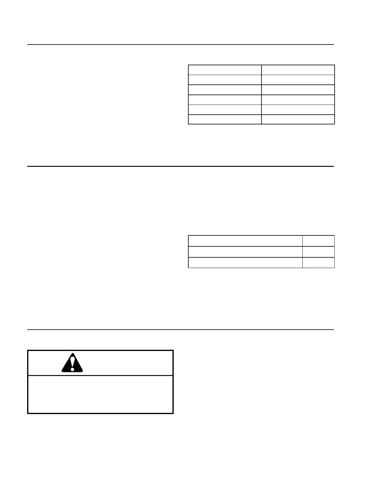
Voltage Measured
Battery Charge Level
12.68 v (or higher) Fully charged (100%)
12.45 v 75% charged
12.24 v 50% charged
12.06 v 25% charged
11.89 v 0% charged
Charging System Test
This is a simple test used to determine if a charging sys-
tem is functioning. It will tell you if a charging system has
an output, but not its capacity.
Tool required: Digital multimeter set to DC volts.
Test instructions: Connect the positive (+) meter lead to
the positive battery post and the negative (−) meter lead
to the negative battery post. Leave the test leads con-
nected and record the battery voltage.
NOTE: Upon starting the engine, the battery voltage
will drop and then should increase once the engine is
running.
NOTE: Depending upon the condition of the battery
charge and battery temperature, the charging system
voltage will increase at different rates as the battery
charges.
Start the engine and run at high idle (3350 to 3450
RPM). Allow the battery to charge for at least three (3)
minutes. Record the battery voltage.
Test results should be at least 0.50 volt over initial bat-
tery voltage. Example:
Initial Battery Voltage
= 12.30 v
Battery Voltage after 3 Minute Charge = 12.95 v
Difference = +0.65 v
NOTE: Typical battery voltage while the engine is run-
ning during this test should be 13.5 to 14.5 volts.
Check Operation of Interlock System
CAUTION
Do not disconnect safety switches. They are for
the operator’s protection. Check the operation of
the interlock switches daily for proper operation.
Replace any malfunctioning switches before op-
erating the machine.
Interlock switch operation is described in the machine
Operator’s Manual. Your machine is equipped with an
Toro Electronic Controller (TEC) which monitors inter-
lock switch (input) operation. If one or more inputs are
not in the correct position to allow certain machine oper-
ations, or are malfunctioning, the fault indicator will illu-
minate and an advisory screen will appear on the
InfoCenter Display (see Operator Advisory Screen and
Operator Advisories in this chapter). Testing of individu-
al interlock switches is included in the Component Test-
ing section of this Chapter.
NOTE: Use the InfoCenter Display (see InfoCenter
Display in this chapter) to test Toro Electronic Controller
inputs and outputs before further troubleshooting of an
electrical problem on your machine.
 Loading...