Multi Pro 1750
Page 5 − 45
Electrical System
Application Rate (Spray Pressure) Switch
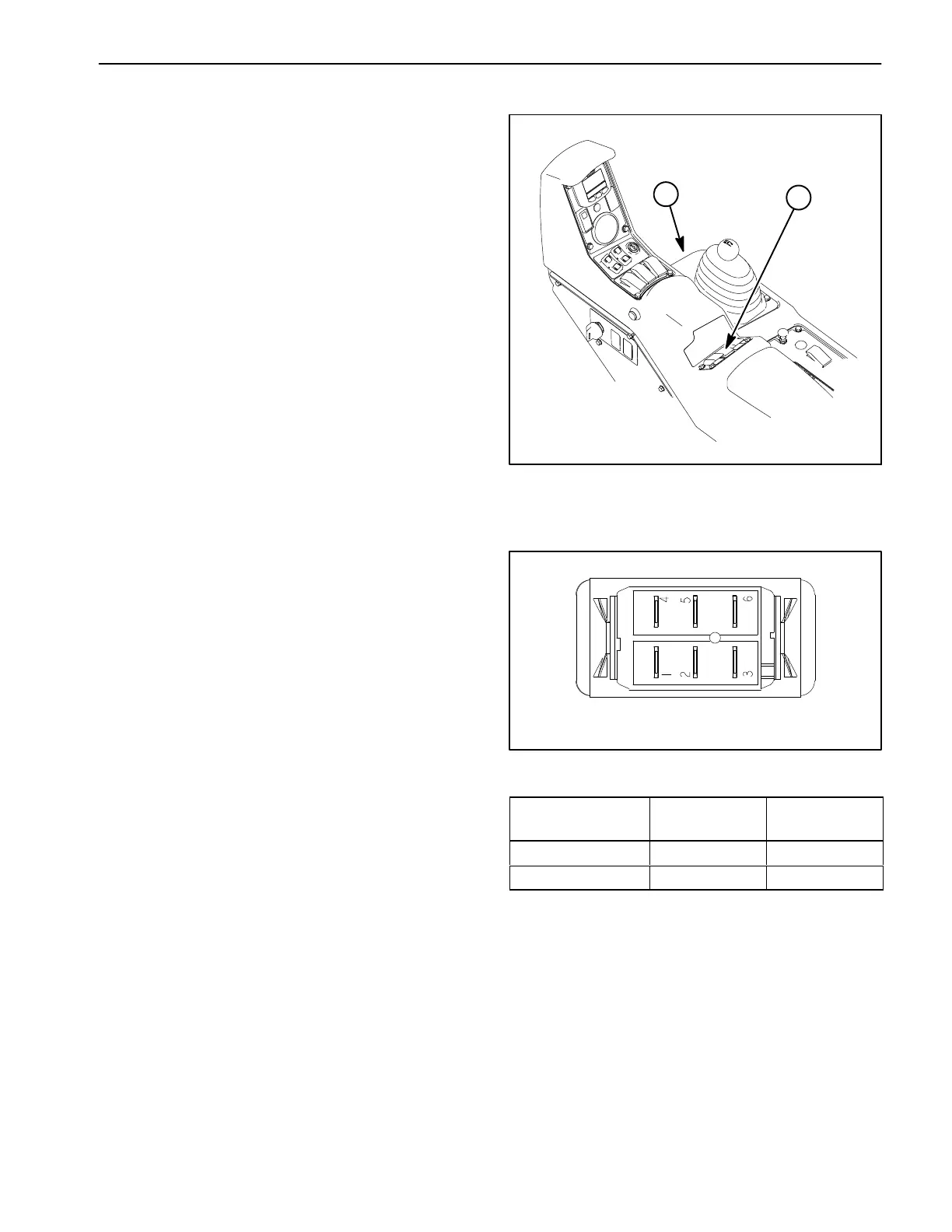
The application rate switch is a three (3) position rocker
switch used to increase or decrease the application rate
(spray system pressure). When the application rate
switch is pressed, the spray system rate valve is adjus-
ted. The application rate switch is located on the control
console (Fig. 53).
NOTE: When the supervisor switch is in the OFF
(locked) position, the application rate switch is disabled.
Testing
1. Park machine on a level surface, stop spray pump,
stop engine and engage parking brake. Remove key
from ignition switch.
2. Remove console panel. Locate the application rate
switch on console and unplug machine wire harness
connector from switch.
3. With the use of a multimeter (ohms setting), the ap-
plication rate switch functions may be tested to deter-
mine whether continuity exists between the various
terminals for each switch position. The switch terminals
are marked as shown (Fig. 54) and the circuitry of the
application rate switch is shown in the chart (Fig. 55).
Verify continuity between switch terminals.
4. Replace application rate switch if testing determines
that it is faulty.
5. If the switch tests correctly and a circuit problem still
exists, check wire harness (see Electrical Schematic
and Wire Harness Drawings in Chapter 10 − Electrical
Drawings in this manual).
6. After testing is completed, connect the harness con-
nector to the application rate switch. Install console pan-
el to machine.
1. Control console 2. Application rate
(spray pressure) switc
Figure 53
1
3
Figure 54
BACK OF SWITCH
SWITCH
POSITION
NORMAL
CIRCUITS
OTHER
CIRCUITS
OFF 2 + 1 5 + 4
ON 2 + 3 5 + 6
Figure 55
 Loading...