Multi Pro 1750 Page 6 − 39 Spray System
Agitation Throttle Valve (Serial Number Above 315000000)
IMPORTANT: Make sure to remove and neutralize
chemicals from spray components before removing
the agitation throttle valve. Wear protective cloth-
ing, chemical resistant gloves and eye protection
during repair.
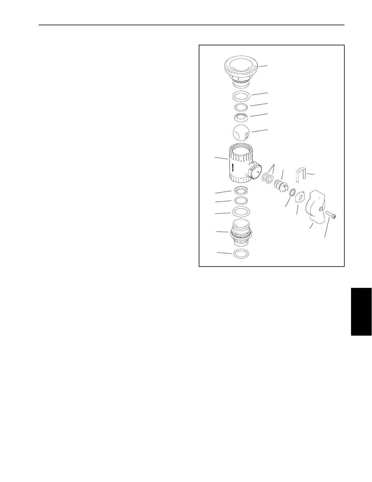
Disassembly (Fig. 25)
1. Remove the screw and the knob from the valve.
2. Remove hoses, fittings, clamps and adapters as
necessary to access valve end caps.
3. Rotate the end caps counterclockwise (unscrew)
and remove the end caps.
4. Rotate the valve stem until the slot in the stem and
valve ball are in−line with the valve body and remove the
valve ball.
5. Remove the valve stem fork, seat, and remove the
valve stem assembly.
Assembly (Fig. 25)
1. Inspect the end cap and the stem seals and O−rings.
Replace components as necessary.
2. Apply silicone grease to seals and O−rings on stem
assembly. Install stem assembly, seat and fork.
3. Rotate the valve stem until the slot in the stem is in−
line with the valve body and install the valve ball.
4. Apply silicone grease to seals and O−rings on end
caps and install end caps. Tighten end caps until seated.
Do not over−tighten end caps.
5. Install hoses, fittings, clamps and adapters previous-
ly removed.
6. Install knob and screw.
1. Valve body
2. End cap
3. Seat (2)
4. O−Ring (2)
5. O−Ring (2)
6. O−Ring
7. Ball
8. Stem fork
9. O−Ring (2)
10. Stem
11. Washer
12. Stem seat
13. Knob
14. Screw
Figure 25
Typical Spray Valve Assembly
1
2
3
4
5
6
7
8
9
10
11
2
3
4
5
12
13
14
Spray
System
 Loading...