Multi Pro 1750
Page 5 − 41
Electrical System
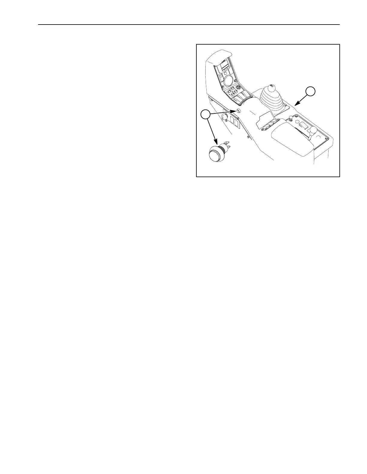
Master Boom (Spray Enable) Switch
The master boom switch is a momentary push button
switch used to turn the master boom valve ON and OFF.
The master boom switch is located on the side of the
control console (Fig. 43).
With the ignition switch in the RUN or START position,
a continuous supply of voltage is applied to terminal 1 or
A (+) and 2 or B (−) of the master boom valve actuator,
closing the master boom valve. The Toro Electronic
Controller (TEC) monitors the operation of the master
boom switch (input). When the master boom switch is
depressed, a momentary ground is created, and if sys-
tem conditions are met, the TEC energizes the master
boom valve output. The output applies voltage to termi-
nal 3 or C (open) of the master boom valve actuator,
opening the master boom valve. An icon will appear on
the InfoCenter Display when the master boom valve is
open (enabled).
NOTE: The master boom (spray enable) switch must
be disengaged or the master boom switch engaged but
none of the boom spray switches engaged to energize
the spray pump clutch.
Testing
The master boom (spray enable switch) and its circuit
wiring can be tested as a TEC input using the InfoCenter
Display (see InfoCenter Display − Diagnostics Screen in
this chapter). If testing determines that the switch and
circuit wiring are not functioning correctly, proceed with
the following test procedure:
1. Park machine on a level surface, stop spray pump,
stop engine and engage parking brake. Remove key
from ignition switch.
2. Remove console panel. Locate master boom switch
and unplug wire harness connector from switch.
3. With the use of a multimeter (ohms setting), the mas-
ter boom switch functions may be tested to determine
whether continuity exists across the terminals for each
switch position. Continuity (zero ohms resistance)
should exist across the switch terminals when the switch
is depressed. There should not be continuity (infinite
ohms resistance) across the switch terminals when the
switch is not depressed.
1. Control console 2. Master boom
(spray enable) switch
Figure 43
1
2
4. Replace master boom switch if testing determines
that it is faulty.
5. If the master boom switch tests correctly and a circuit
problem still exists, check wire harness (see Electrical
Schematic and Wire Harness Drawings in Chapter 10 −
Electrical Drawings in this manual).
6. Connect the wire harness connector to the master
boom switch after testing. Secure console panel to ma-
chine.
 Loading...