Multi Pro 1750 Page 9 − 27 Ultra Sonic Boom Kit (Optional)
NOTE: If TEC for the Ultra Sonic Boom Kit is replaced
for any reason, system software needs to be repro-
grammed by your Toro Distributor.
IMPORTANT: Before performing welding on the ma-
chine, disconnect both cables from the battery and
disconnect wire harness connector from the TEC.
These steps will prevent damage to the machine
electrical system.
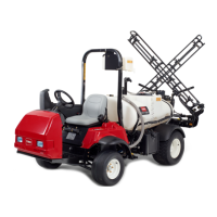
Figure 22
1
11
21
31
41
30
20
10
40
50
NOTE TAB POSITION
WIRE HARNESS CONNECTOR FOR TEC
CAN−bus Termination Resistors
IMPORTANT:The Ultra Sonic Boom Leveling Kit is
not designed to communicate with the machine In-
foCenter. Even though the communication network
is not being used, the termination resistors are re-
quired for proper electrical system operation.
The Toro Electronic Controller (TEC) used for the ultra
sonic boom kit has the ability to communicate with other
components in the machine via a CAN−bus communi-
cation system. Two (2) specially designed, twisted
cables form the bus for the communication network.
When used, these wires provide the data pathways be-
tween machine components. At the ends of the twisted
pair of bus cables are two (2) 120 ohm termination resis-
tors. Even though the network is not being used for the
ultra sonic boom kit, the termination resistors are re-
quired for proper electrical system operation.
The CAN−bus termination resistors plug into the ultra
sonic boom kit wire harness. One of the termination res-
istors is under the operator’s seat near the control con-
sole and the second resistor is located near the ultra
sonic boom kit TEC at the rear of the machine. The wire
harness connectors have a blue insert to identify the
proper location for the termination resistors.
NOTE: Refer to the Ultra Sonic Boom Kit electrical
schematic and wire harness drawings in Chapter 10 −
Electrical Drawings for additional information on ter-
mination resistor location and wire connections.
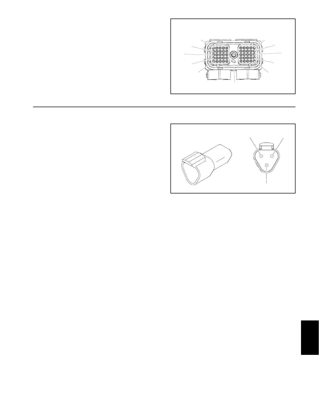
Figure 23
Termination
A
B
C
Resistor
Termination Resistor Test
The termination resistors (Fig. 23) can be tested using
a digital multimeter (ohms setting). There should be 120
ohms resistance between terminals A and B of the ter-
mination resistors. Terminal C is not used on Multi Pro
1750 machines. Replace resistor if testing determines
that it is faulty.
If the resistor tests correctly and a circuit problem still ex-
ists, check wire harness (see Electrical Schematic and
Wire Harness Drawings in Chapter 10 − Electrical Draw-
ings in this manual).
Ultra Sonic
Boom (Opt.)
 Loading...