Multi Pro 1750Page 6 − 34Spray System
Control Valve Service (Serial Number Below 315000000)
The Multi Pro 1750 uses several valves in the spray sys-
tem. Use the following procedure for servicing the agita-
tion, rate, master boom, left spray boom, center spray
boom and right spray boom valves.
IMPORTANT: Make sure to remove and neutralize
chemicals from spray components before valve mo-
tor disassembly. Wear protective clothing, chemical
resistant gloves and eye protection during repair.
NOTE: There are limited replacement parts available
for spray valve assemblies. Check your parts catalog for
parts that are available.
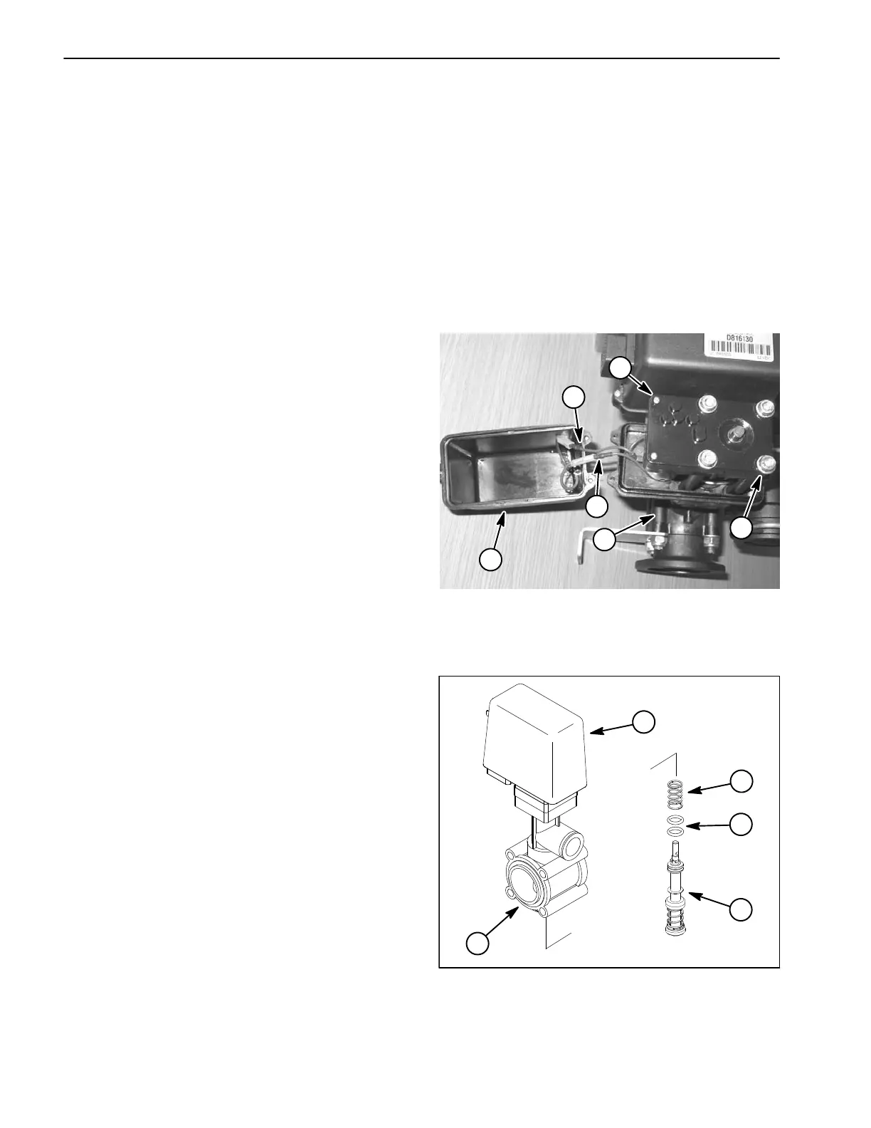
Valve Actuator Cover Removal (Fig. 19)
1. Loosen the three (3) screws that secure the valve ac-
tuator cover to the base assembly.
2. Carefully lift and rotate the cover.
3. Unplug the wire connections between cover and
drive remove the cover.
Valve Actuator Cover Installation (Fig. 19)
1. Make sure that all screws that secure the valve motor
and drive are tight (item 4 and 5).
2. Connect wire connections between actuator cover
and drive. Make sure that cover wire colors are the same
as the drive wire colors when connecting wires.
3. Carefully install cover onto base taking care to not
damage wires and tighten screws.
Piston Assembly Service (Fig. 20)
1. Remove the fork and hose barb from bottom of valve
to allow access to piston assembly.
2. Make sure that valve is closed (piston fully extend-
ed). If valve is not closed, spring above piston assembly
will be under compression and may damage valve mo-
tor or piston assembly during disassembly and assem-
bly. End of piston assembly will extend into bottom of
valve housing when valve is closed. If possible, recon-
nect actuator to machine wire harness and close valve
before removing piston assembly.
3. Rotate the piston assembly counterclockwise to un-
screw it from the valve actuator shaft. Locate and re-
trieve spring (if applicable) from above piston assembly.
4. Inspect seals on piston assembly. If seals in piston
assembly are worn or damaged, replace piston as-
sembly. The piston assembly is not designed to be dis-
assembled so individual components for the assembly
are not available.
5. Apply silicone grease to seals on piston assembly.
6. Position spring into valve motor housing (if applica-
ble). Screw piston assembly onto actuator motor shaft
and tighten.
7. Secure hose barb to bottom of valve motor.
1. Valve base
2. Valve actuator cover
3. Wire connector (2)
4. Socket screw (4)
5. Phillips screw (2)
Figure 19
1
2
5
4
3
3
1. Valve base assembly
2. Piston assembly
3. O−Ring (2)
4. Spring
5. Valve actuator
Figure 20
2
1
4
5
3
 Loading...