Multi Pro 1750
Page 5 − 52
Electrical System
Relays with Five (5) Terminals
Your Multi Pro 1750 uses a number of electrical relays
that have five (5) terminals. The relays are located in the
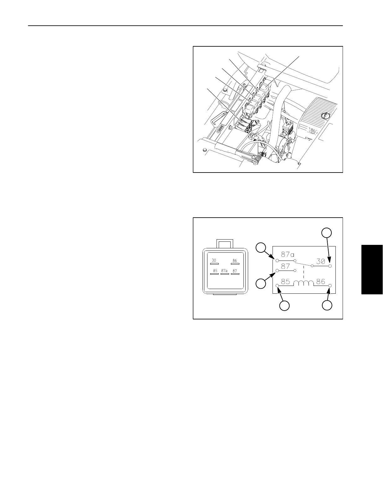
power center compartment of the battery box (Fig. 71).
The start relay is used to provide current to the en-
gine starter motor solenoid. The start relay is ener-
gized by the Toro Electronic Controller (TEC). The
start relay can be identified by a tag at the wire har-
ness connector.
The kill relay is used to provide a complete circuit to
allow the engine starter solenoid to be energized.
When de−energized, the kill relay provides a ground
for the engine magneto system which stops the en-
gine. The kill relay is energized by the TEC. The kill
relay can be identified by a tag at the wire harness
connector.
If the machine is equipped with an optional tank
clean rinse kit, an additional four (5) terminal relay is
added to the electrical system. The rinse kit relay is
energized when the hose reel switch is pressed.
If the machine is equipped with an optional foam
marker kit, an additional four (5) terminal relay is
added to the electrical system. The foam marker
relay is energized when the foam marker power and
control switches are set to ON.
Testing
1. Park machine on a level surface, stop spray pump,
stop engine and engage parking brake. Remove key
from ignition switch.
2. Raise operator seat and locate the relay to be tested.
Disconnect wire harness connector from relay and re-
move relay from panel.
3. The relay terminals are marked as shown (Fig. 72).
NOTE: Prior to taking small resistance readings with a
digital multimeter, short the meter test leads together.
The meter will display a small resistance value (usually
0.5 ohms or less). This resistance is due to the internal
resistance of the meter and test leads. Subtract this val-
ue from from the measured value of the component you
are testing.
4. Using a multimeter, verify that coil resistance be-
tween terminals 85 and 86 is from 71 to 88 ohms.
5. Connect multimeter (ohms setting) leads to relay ter-
minals 30 and 87. Ground terminal 86 and apply +12
VDC to terminal 85. The relay should make and break
continuity between terminals 30 and 87 as +12 VDC is
applied and removed from terminal 85.
1. Fuse blocks
2. Start relay
3. Kill relay
4. Tank clean rinse kit
relay (opt.)
5. Foam marker kit relay
(opt.)
Figure 71
1
2
3
4
5
Figure 72
1
3
2
1. Coil terminal
2. Common terminal
3. Normally closed term.
4. Normally open term.
1
4
6. Disconnect voltage from terminal 85 and multimeter
lead from terminal 87.
7. Connect multimeter (ohms setting) leads to relay ter-
minals 30 and 87A. Apply +12 VDC to terminal 85. The
relay should make and break continuity between termi-
nals 30 and 87A as +12 VDC is applied and removed
from terminal 85.
8. When testing is completed, disconnect voltage and
multimeter leads from the relay terminals. Replace relay
if testing determines that the relay is faulty.
Electrical
System

 Loading...