Multi Pro 1750Hydraulic System Page 4 − 42
Hydraulics Enable Valve
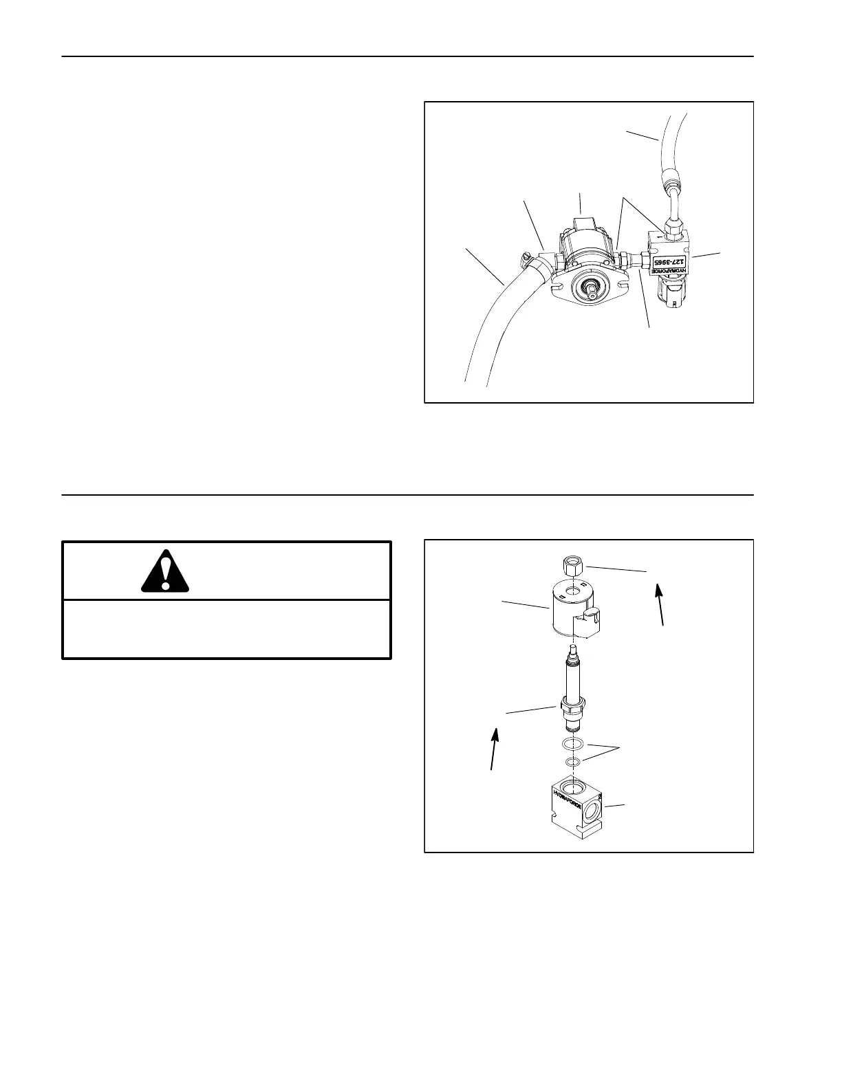
A hydraulic solenoid valve assembly is used on this ma-
chine. When energized, this solenoid valve allows hy-
draulic flow to the steering and boom lift circuits. The
hydraulics enable valve assembly is located near the
gear pump (Fig. 33).
1. Gear pump
2. Hydraulics enable valve
3. Suction hose
4. Hose (to steering valve)
5. Swivel connector
6. Hydraulic fitting
7. Hydraulic fitting
Figure 33
2
1
3
5
4
6
7
Hydraulics Enable Valve Service
CAUTION
Read and follow to the General Precautions for
Removing and Installing Hydraulic System Com-
ponents in this section.
See Cartridge Valve Service in this chapter. Tighten
cartridge valve and solenoid coil nut to specified torque
(Fig. 34).
See Hydraulic Solenoid Valve Coils in Chapter 5 − Elec-
trical System for information on testing the solenoid coil.
Figure 34
1. Nut
2. Solenoid coil
3. Cartridge valve
4. Seal kit
5. Manifold
2
3
1
5
4
25 ft−lb
(34 N−m)
60 in−lb
(6.7 N−m)
 Loading...