Multi Pro 1750
Page 5 − 42
Electrical System
Boom Spray Switches (Serial Number Below 315000000)
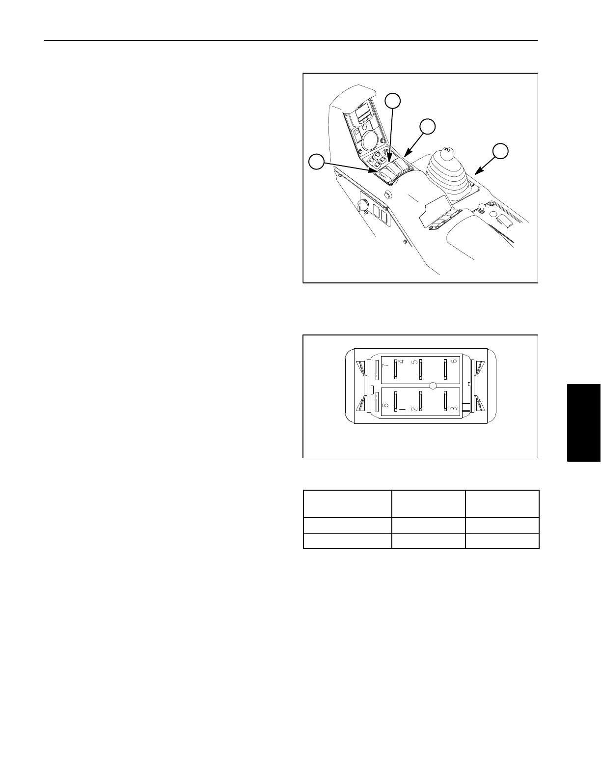
Three (3) identical boom spray switches are used on the
Multi Pro 1750 to turn the spray valve for the individual
boom sections ON or OFF. The boom switches are loc-
ated on the control console (Fig. 44).
With the ignition switch in the START or RUN position,
a continuous supply of voltage is applied to the boom
spray valve actuators, closing the boom spray valves.
When a boom spray switch is set to ON, voltage is sup-
plied to the activator wire of the boom spray valve actua-
tor, opening the boom spray valve. When in the ON
position, the light on the switch will illuminate. The Toro
Electronic Controller (TEC) monitors the operation of
the boom spray switches as inputs. The inputs are used
for counter, timer, and spray calculation purposes.
NOTE: If any of the boom spray switches and the mas-
ter boom (spray enable) switch are engaged, energizing
the spray pump clutch will be prohibited.
Testing
The boom spray switches and the circuit wiring can be
tested as a TEC inputs using the InfoCenter Display
(see InfoCenter Display − Diagnostics Screen in this
chapter). If testing determines that the switches and cir-
cuit wiring are not functioning correctly, proceed with the
following test procedure:
1. Park machine on a level surface, stop spray pump,
stop engine and engage parking brake. Remove key
from ignition switch.
2. Remove console panel. Locate boom spray switch
and unplug machine wire harness connector from
switch.
3. With the use of a multimeter (ohms setting), the
boom spray switch functions may be tested to determine
whether continuity exists between the various terminals
for each switch position. The switch terminals are
marked as shown (Fig. 45) and the circuitry of the boom
spray switch is shown in the chart (Fig. 46). Verify conti-
nuity between switch terminals.
4. Terminals 7 (−) and 8 (+) are used for the indicator
light in the boom spray switch. The light should be illumi-
nated when the switch is in the ON position.
5. Replace the boom spray switch if testing determined
that it is faulty.
1. Control console
2. LH spray boom switch
3. Center boom switch
4. RH spray boom switch
Figure 44
1
2
4
3
Figure 45
BACK OF SWITCH
SWITCH
POSITION
NORMAL
CIRCUITS
OTHER
CIRCUITS
OFF 2 + 1 5 + 4
ON 2 + 3 5 + 6
Figure 46
6. If the boom spray switch tests correctly and a circuit
problem still exists, check wire harness (see Electrical
Schematic and Wire Harness Drawings in Chapter 10 −
Electrical Drawings in this manual).
7. Connect the harness connector to the boom spray
switch after testing. Install console panel to machine.
Electrical
System
 Loading...