Multi Pro 1750
Page 5 − 57
Electrical System
Spray System Valve Actuators (KZ − Serial Number Above 315000000)
The Multi Pro 1750 spray system uses a variety of
valves to control the spray product flow (see Chapter 6
− Spray System in this manual). Each valve has a
12VDC actuator (motor) that can be tested individually.
The master boom, boom section valves, and agitation
valve actuators are controlled using a three (3) wire cir-
cuit. A constant supply of power is applied to terminals
A (+) and B (−), energizing the actuator to close the
valve. Applying power to terminal (C) reverses the direc-
tion of actuator operation, opening the valve.
The rate valve actuator is controlled using a four (4) wire
circuit. A constant supply of power is applied to terminals
A (+) and B (−). Applying power to the open terminal (C)
or the close terminal (D) controls the direction of actua-
tor operation.
Testing
1. Park machine on a level surface, stop spray pump,
stop engine and engage parking brake. Remove key
from ignition switch.
IMPORTANT: Make sure to neutralize and remove
chemicals from pump and hoses before loosening
and removing spray system components. Wear pro-
tective clothing, chemical resistant gloves, and eye
protection during repair.
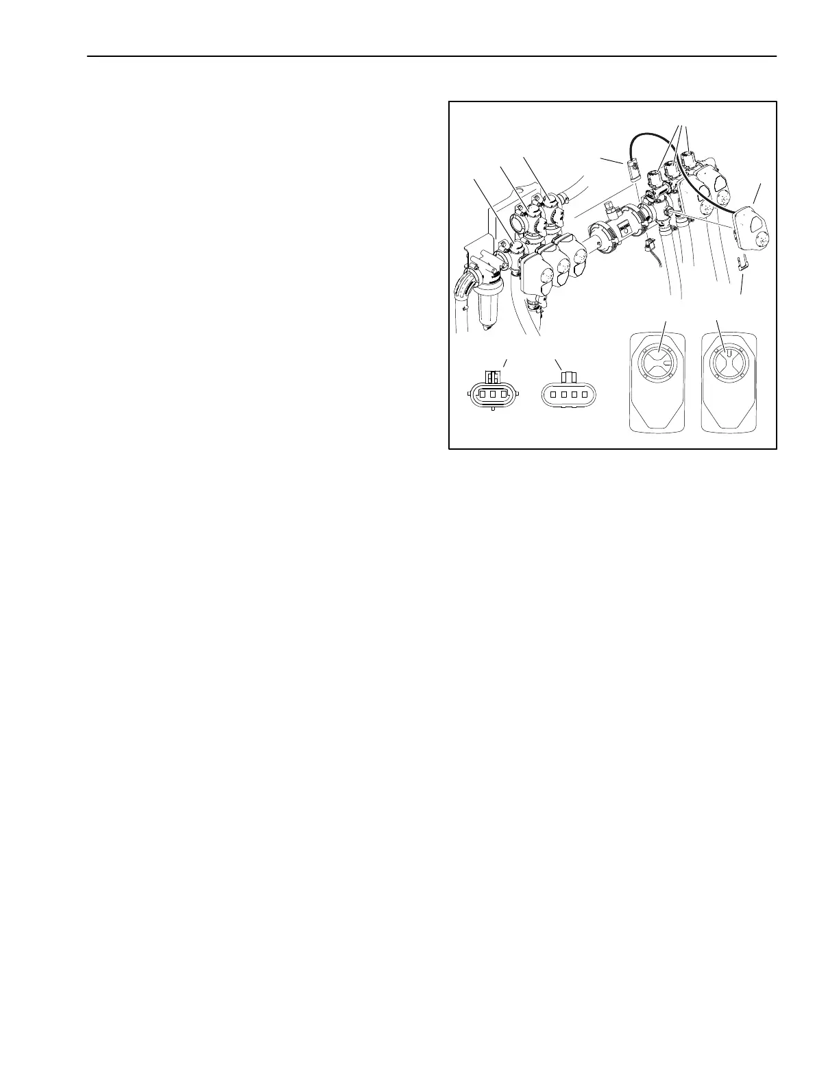
2. Locate valve actuator to be tested (Fig. 76). Care-
fully unplug machine wire harness connector from valve
actuator, remove the retaining fork and remove the actu-
ator from the valve assembly.
Three (3) wire operated actuators:
A. Connect 12VDC to terminal A (+ red wire) and
connect terminal B to ground (− black wire) The actu-
ator should rotate in a clockwise direction, stop, and
a red LED should illuminate.
B. Connect 12VDC to terminal A (+ red wire) and ter-
minal C (open white wire), then connect terminal B to
ground (− black wire). The actuator should rotate in a
counterclockwise direction, stop, and a green LED
should illuminate.
Four (4) wire operated actuators:
A. Connect 12VDC to terminal A (+ red wire) and
connect terminal B to ground (− black wire). The ac-
tuator should not rotate in either direction.
1. Rate valve
2. Agitation valve
3. Master boom valve
4. Boom spray valves (3)
5. Valve actuator
6. Wire harness connector
7. Fork
8. Valve closed (red LED)
9. Valve open (green LED
10. 3 Wire connector
11. 4 Wire connector
Figure 76
1
2
3
4
5
6
7
8
9
10
11
ABC A BCD
B. Connect 12VDC to terminal A (+ red wire) and ter-
minal C (open white wire), then connect terminal B to
ground (− black wire). The actuator should rotate in a
clockwise direction, stop, and a red LED should illu-
minate.
C. Connect 12VDC to terminal A (+ red wire) and ter-
minal D (close green wire), then connect terminal B
to ground (− black wire). The actuator should rotate
in a counterclockwise direction, stop, and a green
LED should illuminate.
3. If actuator dose not operate smoothly in both direc-
tions, replace the actuator.
4. If the actuator tests correctly, test the valve operation
by manually rotating the valve shaft with a screwdriver.
Repair or replace the valve if necessary (see Spray
Valve Service in Chapter 6 − Spray System in this manu-
al).
5. If the actuator and valve test correctly and a circuit
problem still exists, check wire harness (see Electrical
Schematic and Wire Harness Drawings in Chapter 10 −
Electrical Drawings in this manual).
6. Install the valve actuator and connect it to the ma-
chine wire harness after testing is completed.
 Loading...