Multi Pro 1750
Page 5 − 31
Electrical System
Fuses
The fuse blocks are located under the operator seat next
to the battery.
Fuse Identification and Function
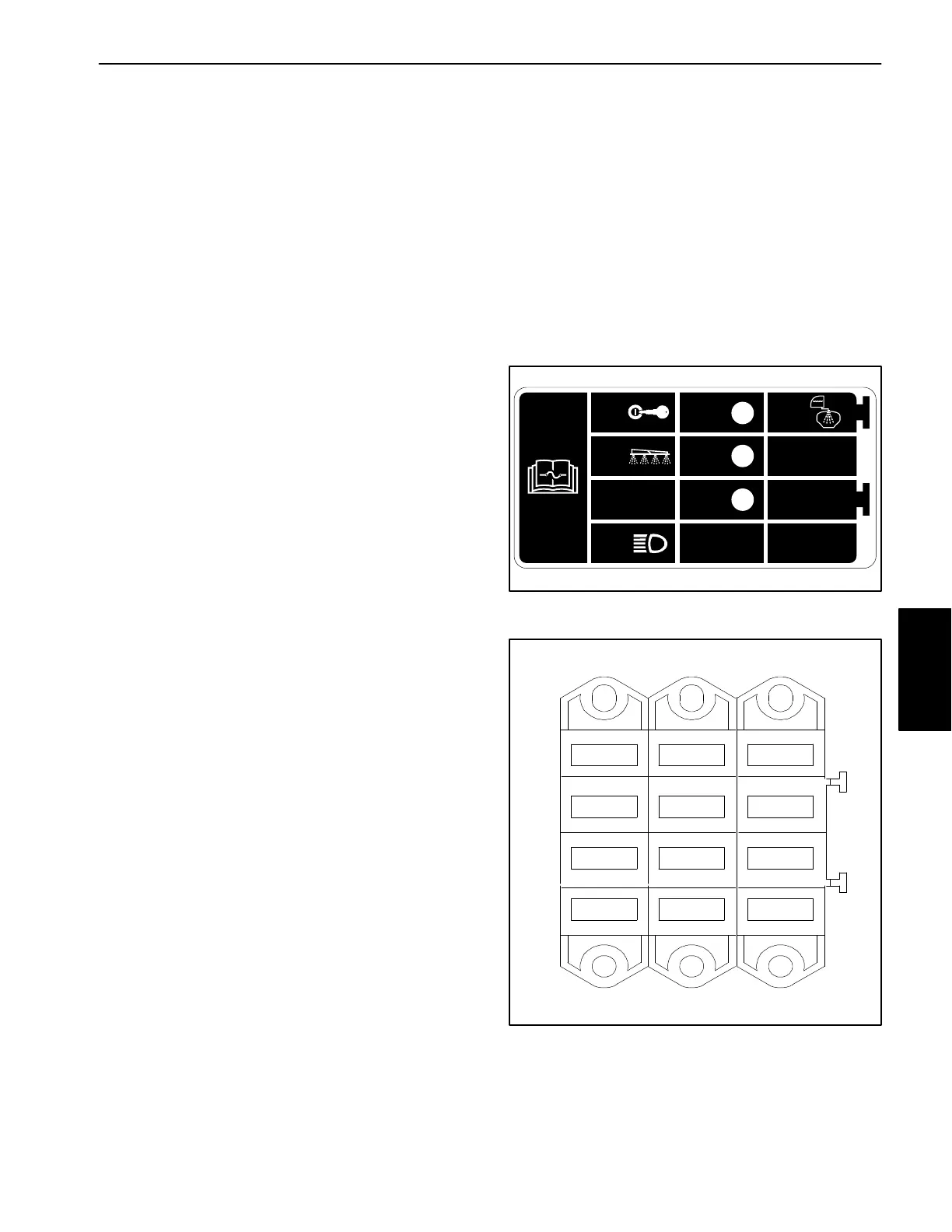
Use the fuse decal (Fig. 28) and fuse block shown in Fig-
ure 29 to identify each individual fuse and its correct am-
perage. The fuses have the following functions:
Left column, top fuse (10 amp) protects ignition switch
circuits.
Left column, 2
nd
from top fuse (15 amp) protects
spray system power circuits.
Left column, 3
rd
from top fuse (15 amp) is available
for optional foam marker kit.
Left column, bottom fuse (15 amp) protects headlight
circuit, InfoCenter power circuit and ground speed
sensor circuit.
Middle column, top fuse (7.5 amp) protects TEC out-
put power supply for engine start relay, engine kill relay,
engine carburetor solenoid, spray pump electric clutch
and spray pump running indicator light. Fault code #2
should be displayed on the InfoCenter Display if this
fuse is faulty.
Middle column, 2
nd
from top fuse (7.5 amp) protects
TEC output power supply for throttle lock coil, throttle
lock indicator light, master spray boom power and op-
tional tank clean rinse kit pump relay. Fault code #2
should be displayed on the InfoCenter Display if this
fuse is faulty.
Middle column, 3
rd
from top fuse (7.5 amp) protects
TEC output power supply for brake lock and optional
brake light. Fault code #2 should be displayed on the In-
foCenter Display if this fuse is faulty.
Middle column, bottom fuse (2 amp) protects logic
power circuit to the TEC.
Right column, top fuse (30 amp) is available for op-
tional tank clean rinse kit.
In−line Fuses (machine serial number 314000001 to
314000999) (5 amp) protect the master spray valve, ag-
itation valve, right spray valve, center spray valve, left
spray valve, and rate valve. The fuses are located in the
wire harness near each valve actuator wire harness
connecter.
Testing
Raise and support operator seat to access fuse blocks.
Turn ignition switch to the ON position (do not start en-
gine). With the fuse installed in the fuse block, use a
multimeter to verify that 12 VDC exists at both of the ter-
minal test points on the fuse. If 12 VDC exists at one of
the fuse test points but not at the other, the fuse is faulty.
If necessary, make sure that ignition switch is OFF and
key is removed from switch. Remove fuse from fuse
block and check that fuse has continuity across the fuse
terminals.
Figure 28
15A
15A
10A
7.5A
2A
7.5A
7.5A
30A
2
3
4
TEC
15A (opt.)
Figure 29
7.5A
7.5A
2A
30A
7.5A
15A
15A
10A
15A (opt.)
Electrical
System

 Loading...