Section 3 - Service & Repair Cylinders
505115-000 Pa
e 3-17
S
TEERING
C
YLINDER
R
EMOVAL
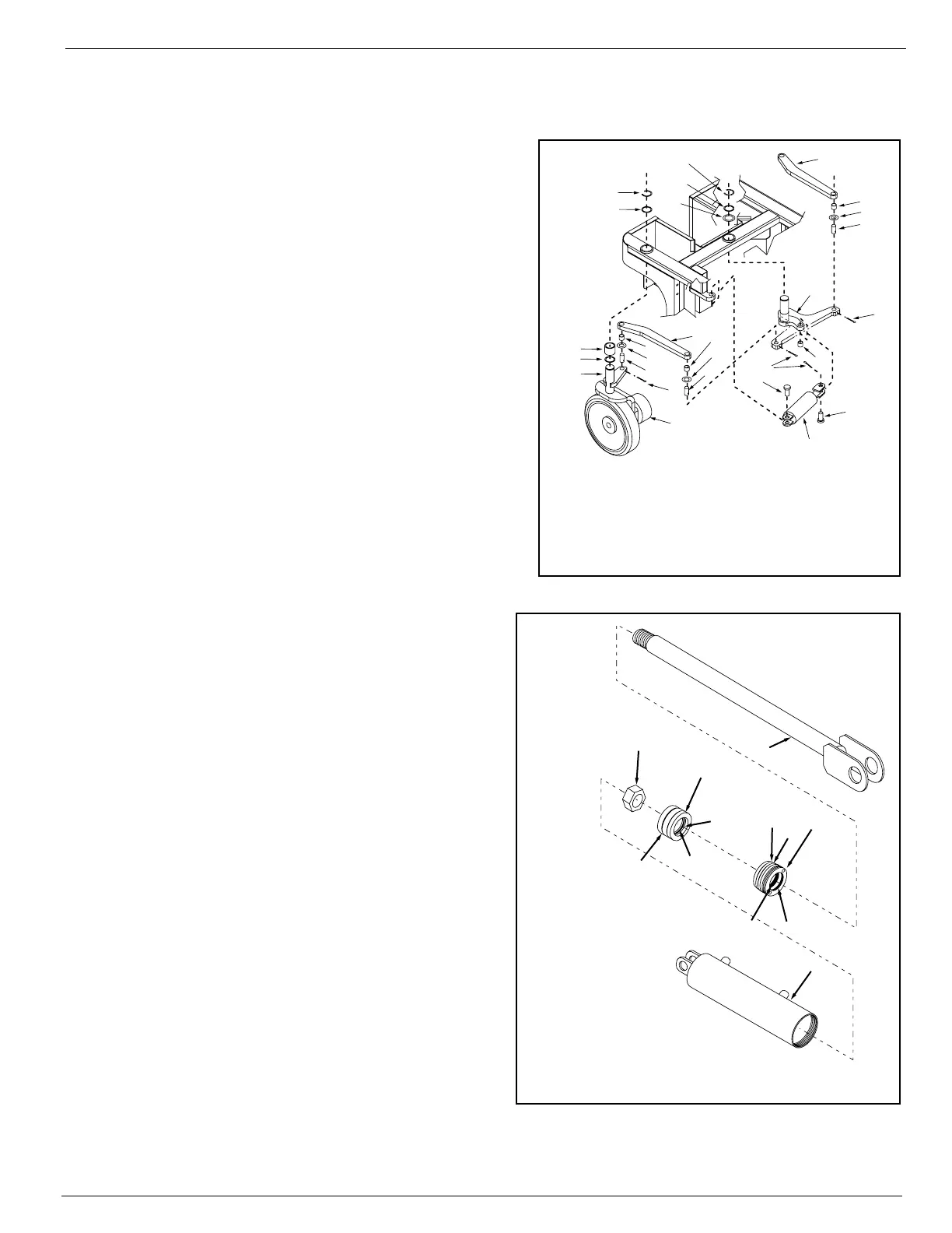
Figure 3-12: Steering Cylinder Remove & Replace
1. Mark and disconnect the hose assemblies from
the cylinder fittings and immediately cap the
openings to prevent foreign material from enter-
ing.
2. Remove the cotter pins from the pivot pins.
3. Remove the pivot pins while supporting the cylin-
der. Remove the cylinder.
R
EPAIR
Refer to Cylinder Repair in
Section 1 - General Information.
I
NSTALLATION
1. Position the cylinder assembly in the chassis and
insert pivot pins and secure with new cotter pins.
2. Connect the hose assemblies to the fittings.
3. Operate the steering circuit several times
throughout its entire range of travel to expel
trapped air and check for leaks.
Figure 3-13: Brake and Steering Cylinder Seal Kit
1
2
3
4
5
10
8
8
9
10
10
10
11
11
11
12
12
14
14
15
13
13
13
15
12
7
6
5
1. Steering Link, Right
2. Steering Link, Left
3. Bell Crank Weldment
4. Steering Cylinder
5. Pivot Pin
6. Drive Motor
7. Wheel Yolk
8. Thrust Washer 1 ½”
9. Bearing, 1 ½” ID
10. Bearing, ¾” ID
11. Thrust Washer, ¾”
12. Steer Pin
13. Cotter Pin
1
5
4
G (2) A
B
3
E, F
H
D
C
2
1. Shaft
2. Cylinder Barrel
3. Head Cap
4. Piston
5. Piston Nut
A. O-Ring
B. Backup Ring
C. Rod Wiper
D. U-Cup
E. Teflon Piston Ring
F. O-Ring (under Piston Ring)
G. Backup Ring (2)
H. O-Ring

 Loading...


