I/O Board Inputs and Outputs Section 4 - Troubleshooting
Pa
e 4-10 505115-000
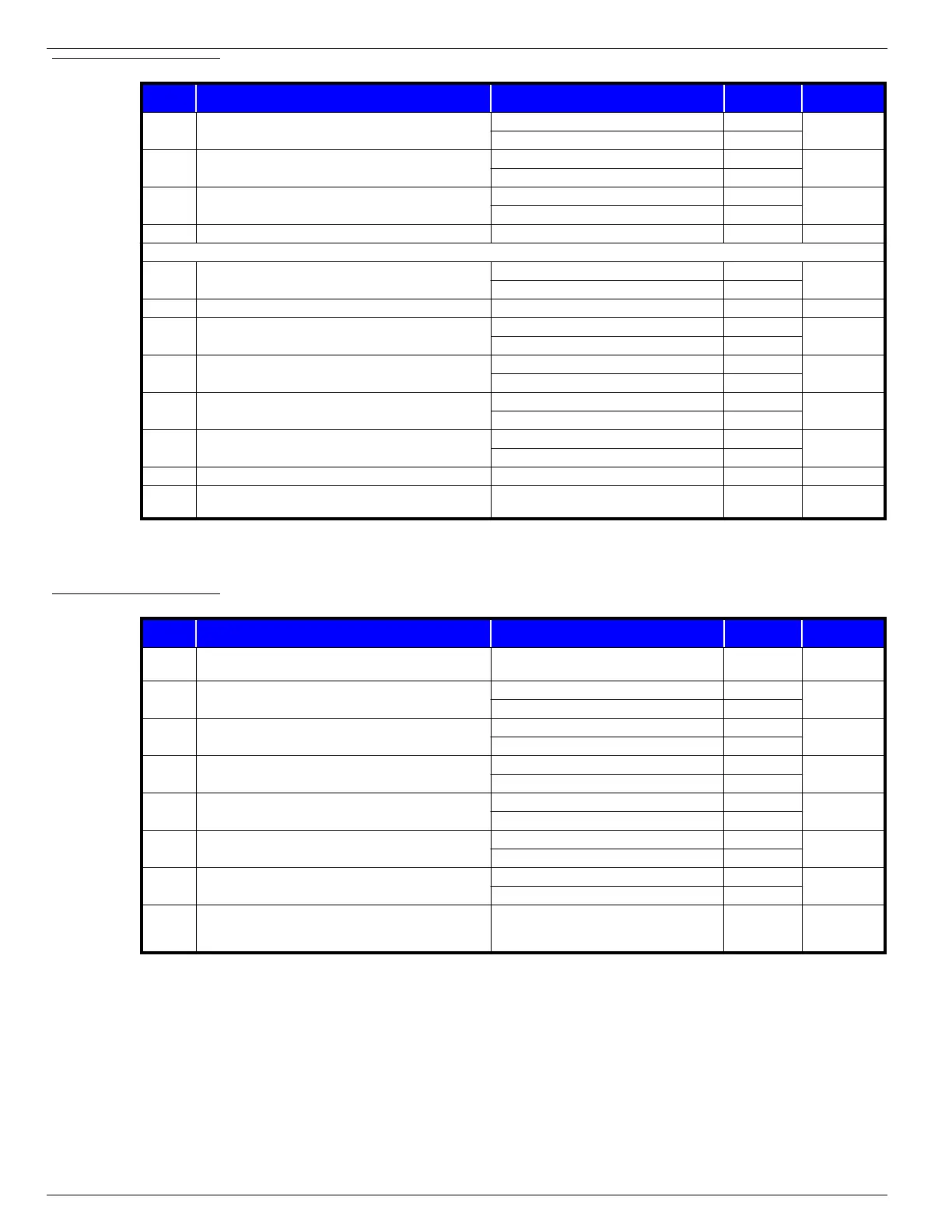
Table 4-5:
Connector J4
Table 4-6:
Connector J5
PIN PIN DESCRIPTION CONDITION VOLTAGE
CONTINUOUS
TO PIN
J4-1 Motor Start relay and Hourmeter activation
Drive, Lift or Steer requested 0V
—
Drive, Lift or Steer not requested BV
J4-2 24 Volt supply to Keyswitch
Upper & Lower E-Stops closed BV
—
Upper or Lower E-Stop open 0V
J4-3 Chassis Controls selected from Keyswitch
Chassis Controls selected BV
—
Chassis Controls not selected 0V
J4-4 24 Volt supply to chassis Up/Down switch —‡—
‡ Keyswitch must be held to Chassis Controls position to measure BV
J4-5 24 Volt supply to Keyswitch
Upper & Lower E-Stops closed BV
J2-3 & J3-3
Upper or Lower E-Stop open 0V
J4-6 Not Used ———
J4-7 Up signal from Chassis Controls
Up requested from Chassis Controls BV
—
Up not requested from Chassis Controls 0V
J4-8 Down signal from Chassis Controls
Down requested from Chassis Controls BV
—
Down not requested from Chassis Controls 0V
J4-9
Lower E-Stop activation
(input to I/O board when E-Stop is closed)
Lower E-Stop closed BV
J1-4
Lower E-Stop open 0V
J4-10 Power output to Platform Controls
Platform selected at Keyswitch BV
J1-6
Platform not selected at Keyswitch 0V
J4-11 Battery negative supply to I/O Board — B–—
J4-12 24 Volt supply to Hourmeter and Line Contactor coil
Upper & Lower E-Stops closed and
Platform Controls or Chassis Controls selected
BV —
PIN PIN DESCRIPTION CONDITION VOLTAGE
CONTINUOUS
TO PIN
J5-1 24 Volt supply to EMC motor controller
Upper & Lower E-Stops closed and
Platform Controls or Chassis Controls selected
BV —
J5-2 Drive signal to EMC motor controller
Forward/Reverse requested 15V
—
Forward/Reverse not requested 0V
J5-3 Steer signal to EMC motor controller
Steer Right/Steer Left requested 15V
—
Steer Right/Steer Left not requested 0V
J5-4 Up signal to EMC motor controller
Up requested 15V
—
Up not requested 0V
J5-5 Speed Reduction signal to EMC motor controller
Below Proximity switch 15V - 17V
—
Above Proximity switch 0V
J5-6 Line Contactor activation signal
Drive, Lift or Steer requested 0V
—
Drive, Lift or Steer not requested BV
J5-7 Direction enable
Forward/Reverse requested 0V
—
Forward/Reverse not requested 4.0V - 4.3V
J5-8 Speed signal to EMC motor controller
Signal starts high and drops proportionally as
Control Handle is moved in either direction
4.3V
dropping to
0.2V
—

 Loading...


