Tilt Sensor Section 3 - Service & Repair
Pa
e 3-24 505115-000
3-11 T
ILT
S
ENSOR
WARNING
!
!
Never perform service on the work platform in the elevating assembly area while platform is elevated
without first blocking the elevating assembly.
DO NOT stand in elevating assembly area while deploying or storing brace.
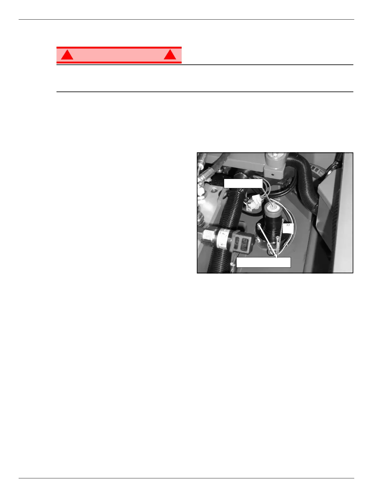
The Tilt Sensor has three wires; red-power (24v in), black-ground, white-output (24v out). To verify the
sensor is working properly, there is one red LED under the sensor. If the LED is on, the sensor is off level.
Figure 3-18: Tilt Sensor
A
DJUSTMENT
1. Place machine on firm level surface ±¼°.
2. Use the Inclinometer
(p/n 010119-000) to ensure front and rear of
Chassis is level ±¼°.
3. Adjust the three leveling screws until the
bubble is centered in the circle on the
attached bubble level.
T
EST
1. Raise the platform approximately 2m (7 ft.).
2. Support the elevating assembly (see “Sup-
porting Elevating Assembly” on
page Section 3-3).
3. Push the level sensor to the side.
The red LED should turn on, and the tilt alarm should sound.
Adjusting Screws
Bubble Level

 Loading...


