Section 4 - Troubleshooting I/O Board Inputs and Outputs
505115-000 Pa
e 4-9
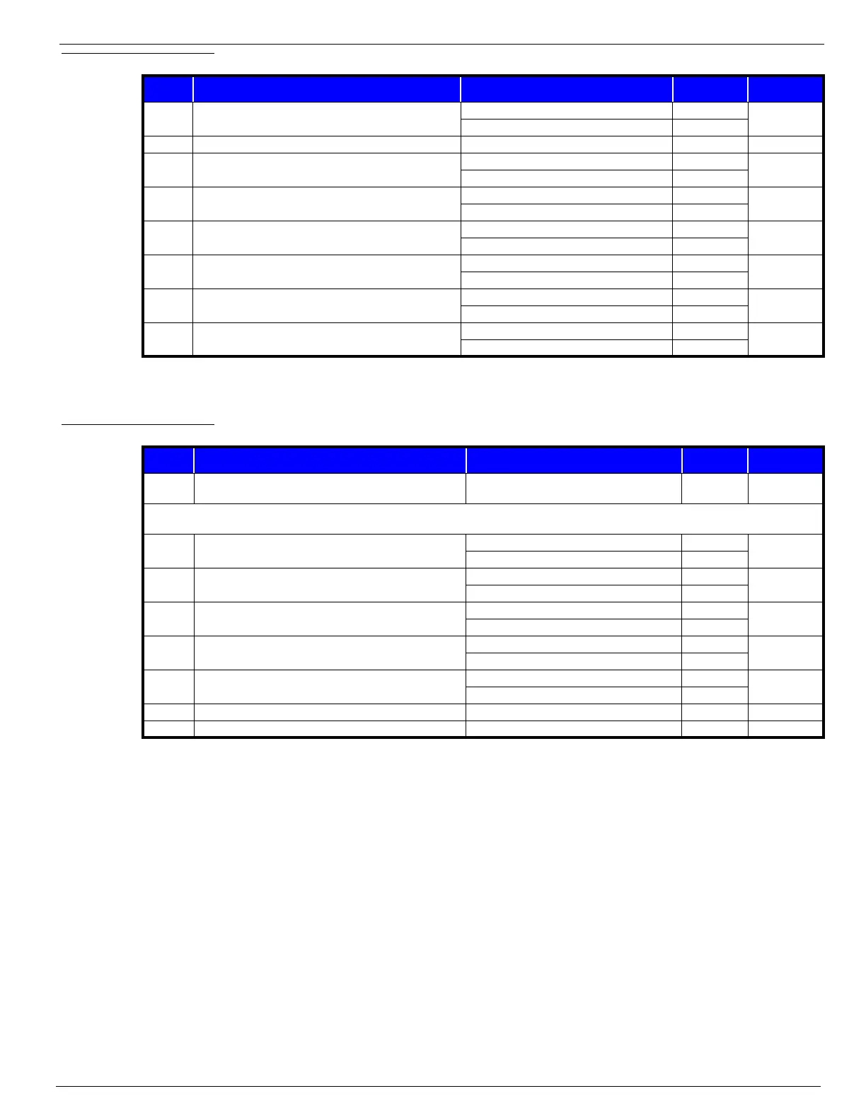
Table 4-3:
Connector J2
Table 4-4:
Connector J3
PIN PIN DESCRIPTION CONDITION VOLTAGE
CONTINUOUS
TO PIN
J2-1 Depression mechanism activation (extend)
Lift Up requested 0V
—
Lift Up not requested BV
J2-2 Not Used ———
J2-3 24 Volt supply for solenoids
Upper & Lower E-Stops closed BV
J4-5 & J3-3
Upper or Lower E-Stop open 0V
J2-4 Forward solenoid activation
Forward requested 0V
—
Forward not requested BV
J2-5 Reverse solenoid activation
Reverse requested 0V
—
Reverse not requested BV
J2-6 Up solenoid activation
Up requested 0V
—
Up not requested BV
J2-7 Steer Left solenoid activation
Steer Left requested 0V
—
Steer Left not requested BV
J2-8 Steer Right solenoid activation
Steer Right requested 0V
—
Steer Right not requested BV
PIN PIN DESCRIPTION CONDITION VOLTAGE
CONTINUOUS
TO PIN
J3-1 Alarm activation
Alarm sounding
(out of level unit lowering, etc.)
†—
† If the alarm is sounding because the unit is out of level, BV will drop to 0V as long as the alarm is sounding.
If the alarm is sounding because the unit is lowering, there will be alternating high and low voltages (the voltages will vary).
J3-2 Tilt Sensor output signal
Unit within Level Sensor angle BV
—
Unit outside Level Sensor angle 0V
J3-3 24 Volt supply for Alarm, Tilt Sensor and solenoids,
Upper & Lower E-Stops closed BV
J2-3 & J4-5
Upper or Lower E-Stop open 0V
J3-4 Input from platform down Proximity Switch
Above Proximity switch 0V
—
Below Proximity switch BV
J3-5 Down solenoid activation
Down requested 0V
—
Down not requested BV
J3-6 Depression mechanism activation (retract)
Drive requested 0V
—
Drive not requested BV
J3-7 Not Used ———
J3-8 Battery negative supply for Tilt sensor and Proximity switch — B– J4-11

 Loading...


