I/O Board Inputs and Outputs Section 4 - Troubleshooting
Pa
e 4-8 505115-000
4-8 I/O B
OARD
I
NPUTS
AND
O
UTPUTS
Refer to Figure Figure 4-5: “I/O Board,” on pageSection 4-7.
P
ERFORM
T
ESTS
WITH
F
ULLY
C
HARGED
B
ATTERIES
Battery state of charge will affect readings.
BV = B
ATTERY
V
OLTAGE
Readings within a few volts of current battery state of charge will be called BV.
0V
0V is generally 0 up to 1 volt.
V
OLTAGE
R
EADINGS
FOR
E
LECTRONICS
ARE
R
ARELY
E
XACT
Many factors can affect readings, such as state of charge, voltage drops through switches (mechanical or
electrical), and wires.
Be sure that both the Platform and Chassis Emergency Stop Switches are pulled out to the ON position.
All voltages are measured between the component and the B– terminal on the Motor Controller.
NOTE: For the I/O board to be powered up (Green LED illuminated), both E-Stops must be closed and either
Platform Controls or Chassis Controls selected by the Keyswitch.
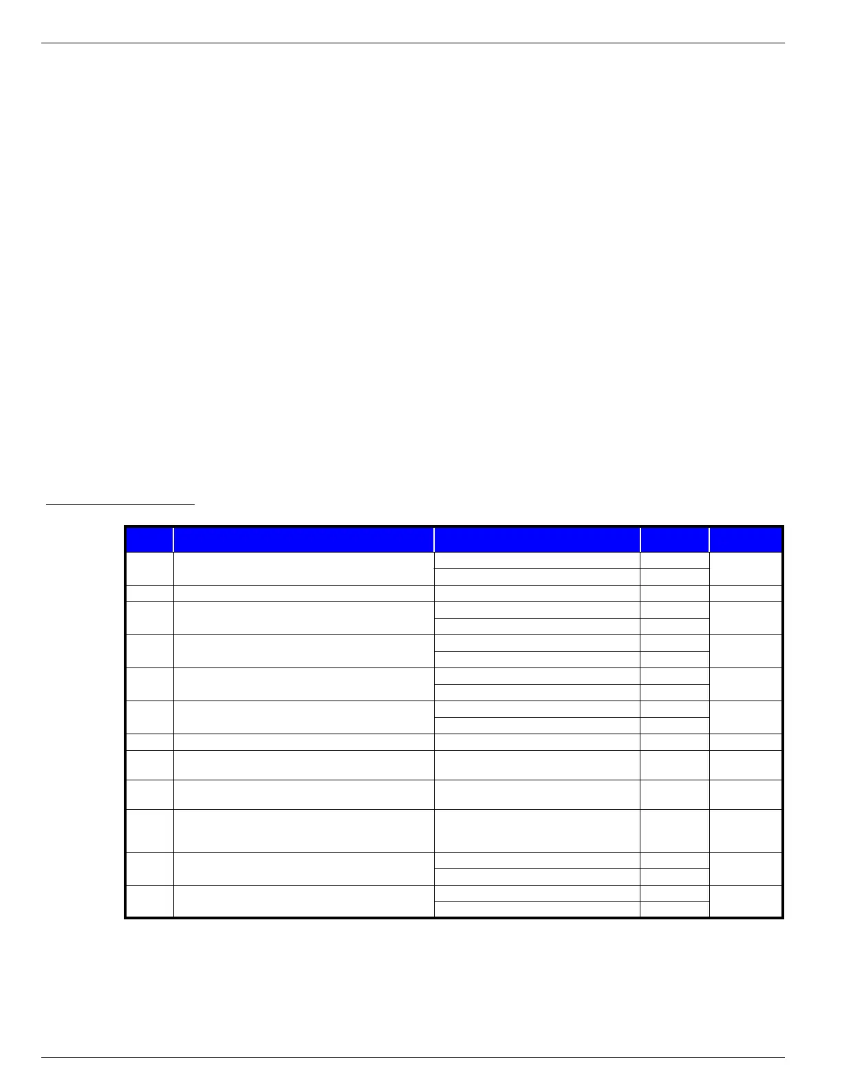
Table 4-2:
Connector J1
PIN PIN DESCRIPTION CONDITION VOLTAGE
CONTINUOUS
TO PIN
J1-1 Lift input from Lift/Drive selector switch
Lift selected BV
—
Lift not selected 0V
J1-2 Not Used ———
J1-3 Drive input from Lift/Drive selector switch
Drive selected BV
—
Drive not selected 0V
J1-4
Lower E-Stop activation
(output from I/O board when lower E-Stop is closed)
Lower E-Stop closed BV
J4-9
Lower E-Stop open 0V
J1-5
Upper E-Stop activation
(output to I/O board when upper E-Stop is closed)
Upper E-Stop closed BV
J4-2
Upper E-Stop open 0V
J1-6 Power to Platform Controls when selected by Keyswitch
Platform Controls selected BV
J4-10
Platform Controls not selected 0V
J1-7 Not Used ———
J1-8
Controller direction “A”
(up/forward)
Control Handle pushed forward 20-22V —
J1-9
Controller direction “B”
(down/reverse)
Control Handle pushed forward 20-22V —
J1-10 Speed signal from Control Handle
Signal starts high and drops proportionally as
Control Handle is moved in either direction
4.3V
dropping to
0.2V
—
J1-11 Steer Left input from Steering switch
Steer Left selected 23V
—
Steer Left not selected 0V
J1-12 Steer Right input from Steering switch
Steer Right selected 23V
—
Steer Right not selected 0V

 Loading...


